

Views: 0 Author: Site Editor Publish Time: 2026-10-15 Origin: Site
Heavy fuel oil (HFO) offers a highly cost-effective energy source for demanding industrial operations. However, it remains inherently unstable in its raw state. Precise viscosity control forms the dividing line between efficient combustion and catastrophic system failure. The physical properties of HFO directly challenge the mechanical limitations of atomization nozzles. They also test the daily endurance of high-pressure fuel pumps. Thick, unconditioned oil simply cannot burn cleanly or safely inside a combustion chamber.
Operating a modern facility requires moving far beyond basic temperature control. Engineers must implement verifiable, real-time kinematic viscosity management to ensure operational stability. This strategic shift guarantees optimal fuel atomization and prevents unexpected mechanical shutdowns. You will learn exactly how fluid mechanics impact burner efficiency. We will explore the core technologies needed for dynamic viscosity control. You will also discover practical steps for upgrading your combustion systems to handle volatile fuel batches reliably.
Viscosity directly dictates droplet size during atomization; incorrect viscosity leads to incomplete combustion, soot buildup, and elevated emissions.
Temperature is a proxy, not a guarantee: Fuel batch variations mean a static heating temperature rarely yields a consistent target viscosity (typically 15–20 cSt).
Modern Heavy Fuel Oil Burner systems require integrated in-line viscometers and dynamic heating loops to maintain compliance and stabilize OPEX.
Evaluating a burner upgrade involves assessing the robustness of its pre-heating skid, pump cavitation prevention, and atomization technology.
The core objective of any Heavy Oil Burner is to shear liquid fuel into a highly combustible fine mist. We call this process atomization. It increases the surface area of the fuel exponentially. This massive surface area allows oxygen to mix rapidly with the combustible hydrocarbons. Kinematic viscosity, measured in Centistokes (cSt), determines the liquid's resistance to this mechanical shear. Viscosity acts as the primary physical variable affecting the final droplet diameter. If you fail to control this resistance, the atomization process breaks down completely.
When you feed cold, highly viscous oil into the nozzle, you trigger a cascade of combustion failures. Thick oil resists the shearing forces of the atomizer. Consequently, the burner produces abnormally large fuel droplets. Large droplets take significantly longer to vaporize and ignite. This delayed ignition pushes the combustion process deeper into the furnace chamber. The elongated flame often causes direct flame impingement on the rear boiler walls. Furthermore, large droplets cannot burn completely before exiting the combustion zone. They leave behind unburned carbon in the form of soot and heavy coke. These deposits rapidly foul the system, coating heat transfer surfaces and blocking flue gas passages.
Operators sometimes overcompensate by applying excessive heat. Thinning the oil too much introduces a different set of severe risks. Extremely low viscosity causes the fuel to undergo premature vaporization inside the nozzle itself. We refer to this condition as flashing. Flashing destroys the spray pattern and creates highly unstable flame geometry. The flame may pulse violently or extinguish unexpectedly. Beyond the burner nozzle, over-heated oil damages the fuel delivery infrastructure. Fuel pumps rely on the natural lubricity of the oil to protect their internal gears. When viscosity drops too low, the oil loses its lubricating properties. This causes severe metal-on-metal wear and induces destructive pump cavitation.
Industry standards mandate a specific viscosity sweet spot for optimal HFO combustion. You must generally maintain the fuel between 10 cSt and 25 cSt right at the nozzle inlet. The exact number depends heavily on your specific nozzle design and atomization method. Mechanical pressure-jet atomizers usually require tighter control near 15 cSt. Air-assist and steam-assist atomizers offer slightly more forgiveness, operating comfortably up to 25 cSt. Maintaining this narrow window requires continuous, active monitoring.
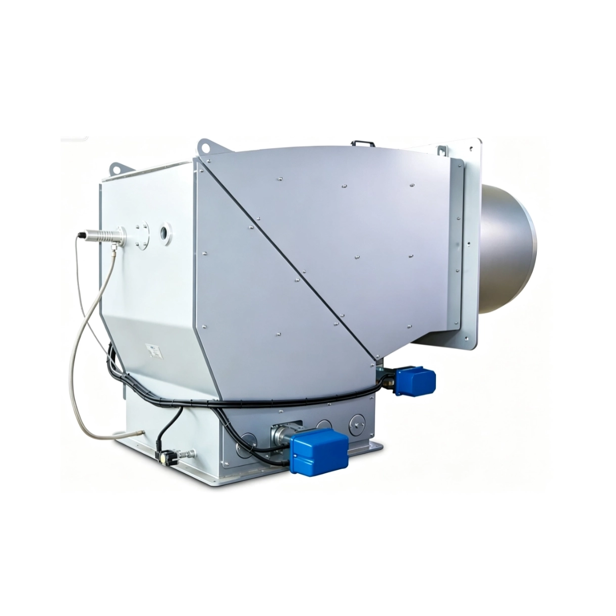
Poor viscosity control rarely remains a hidden problem. It quickly manifests as severe operational bottlenecks and financial drains. Plant managers must recognize these symptoms early to prevent long-term equipment damage. The financial consequences of ignoring fuel conditioning compound rapidly across three major areas.
Inadequate atomization accelerates the physical degradation of expensive furnace components. When elongated flames impinge on boiler walls, the intense localized heat destroys refractory linings. Replacing refractory material requires extended facility downtime and massive labor costs. Additionally, poor combustion generates heavy soot that clogs burner nozzles. Maintenance teams must halt production frequently to pull the burner out and manually scrape coke deposits from the atomizer head. These unplanned maintenance cycles destroy operational efficiency.
Incomplete combustion directly translates to wasted fuel volume. When large oil droplets fail to burn completely, you literally send unburned energy up the exhaust stack. To maintain the required thermal output, operators must pump higher volumes of fuel into the system. This inefficiency becomes exceptionally costly in a Heavy Oil Thermal Heater Burner. Thermal fluid systems require highly stable heat transfer to prevent localized degradation of the diathermic oil. Wasting raw fuel while simultaneously risking the degradation of your thermal fluid creates a double financial penalty.
Environmental regulatory bodies monitor industrial emissions strictly. Incorrect fuel viscosity drastically alters your emissions profile. Heavy droplets generate high levels of unburned particulate matter (PM). The resulting black smoke acts as a visible indicator of process failure. Furthermore, unstable combustion temperatures lead to unpredictable nitrogen oxide (NOx) and sulfur oxide (SOx) formation. Exceeding your permitted emissions thresholds triggers immediate regulatory fines. In severe cases, local authorities will mandate complete facility shutdowns until you resolve the combustion instability.
Solving viscosity fluctuations requires a comprehensive engineering approach. You cannot rely on isolated components. Modern facilities utilize interconnected technologies to prepare the fuel before it ever reaches the combustion chamber.
Effective viscosity management starts with robust thermal input. You must utilize both primary and secondary heating stages.
Primary Bulk Heating: Steam-jacketed heaters excel at raising the bulk temperature of oil moving from the main storage tanks. They handle large volumes efficiently but react slowly to sudden flow changes.
Secondary Trim Heating: Electric outflow heaters sit closer to the burner. They provide rapid, precise temperature adjustments just before atomization. This dynamic response stabilizes the fluid immediately before it enters the nozzle.
Older systems relied on static temperature-to-viscosity charts. Operators would set a thermostat to 120°C and assume the oil reached 15 cSt. This assumption fails today because modern HFO batches vary wildly in chemical composition. A temperature setting that achieves perfect viscosity on Monday might produce dangerous under-heating on Thursday. Modern architectures discard thermostats in favor of active in-line viscometers. Vibrating-fork and resonant viscometers insert a probe directly into the fuel flow. As the fluid thickens, it dampens the vibration of the probe. The sensor measures this mechanical resistance and calculates the true kinematic viscosity in real-time. It then commands the electric trim heater to adjust its output continuously.
Even with perfect heating loops, minor viscosity micro-fluctuations can occur. Advanced atomization technologies help bridge this gap. Standard pressure-jet nozzles rely purely on fluid pressure to shear the oil. They are highly sensitive to viscosity changes. Conversely, air-assist and steam-assist atomizers introduce a secondary high-velocity fluid (compressed air or steam) to tear the oil droplets apart. This secondary shear force easily compensates for slight increases in oil thickness, ensuring a stable flame even during minor heating lags.
When upgrading aging equipment, buyers face a crowded market of competing claims. You must evaluate potential systems methodically. Use a structured decision framework to separate modern, capable systems from outdated designs.
A new burner cannot function as an isolated island. Assess whether the proposed burner control panel integrates natively with your existing Supervisory Control and Data Acquisition (SCADA) or Building Management System (BMS). The system must support a closed-loop control architecture. It should continuously feed live viscosity data back to the central control room, allowing operators to monitor trends and anticipate heating element failures before the flame destabilizes.
Global fuel supply chains remain volatile. Your upgraded Heavy Fuel Oil Burner must handle varying grades of HFO seamlessly. It should also process complex residual blends and alternative liquid fuels. Evaluate the burner's mechanical design closely. A superior system manages different fuel characteristics through automated air-fuel ratio adjustments and dynamic heating profiles. You should never have to perform physical nozzle swaps merely because your fuel supplier delivered a slightly heavier batch of oil.
The fuel delivery skid matters just as much as the burner head. Verify the inclusion of heavy-duty positive displacement pumps. These pumps must confidently push thick, cold oil during challenging startup sequences. Additionally, inspect the pressure-regulating valves. They must feature robust internal seals capable of handling high-viscosity resistance without bypassing or leaking. Weak valves will cause pressure drops that ruin the atomization spray pattern.
Do not accept vague performance promises. Ensure the proposed system features verifiable turndown ratios guaranteed by the manufacturer. Ask for empirical viscosity-control data from similar field installations. The vendor must prove that their active viscosity management loop actually delivers the claimed reductions in particulate matter and NOx emissions across the entire operating range.
System Feature | Basic Legacy Burners | Advanced Modern Burners |
|---|---|---|
Viscosity Control | Static Thermostat (Estimated) | In-line Viscometer (Real-time active loop) |
Atomization Method | Standard Pressure-Jet | Steam/Air-Assist (High tolerance) |
Pump Architecture | Standard Gear Pump | Positive Displacement (High torque) |
Control Integration | Standalone Relay Logic | Native SCADA / BMS Integration |
Purchasing the right equipment only solves half the problem. The physical installation and commissioning phases introduce specific engineering challenges. You must proactively manage these rollout realities to achieve a successful startup.
Starting an HFO system from a cold state presents severe difficulties. Heavy oil crystallizes and solidifies inside unheated pipelines when the system shuts down. If you attempt to pump this solidified mass, you will immediately shear your pump shafts or blow your seals. You must install proper heat tracing along every inch of the pipe. Apply electrical heat trace cables or steam jackets continuously from the main day tank directly to the burner head. Insulate these lines heavily to prevent thermal bridging and cold spots.
In-line viscometers provide critical data, but they operate in brutal environments. Raw HFO contains abrasive particulates and sticky asphaltic compounds. These elements eventually coat the vibrating forks of the viscosity sensor. When fouling occurs, the sensor reads artificially high viscosity levels, causing the system to over-heat the oil dangerously. Establish a strict preventative maintenance schedule. Technicians must pull, clean, and recalibrate the sensors periodically to maintain the integrity of the closed-loop control.
You cannot simply bolt a new burner into place and press start. Post-installation commissioning requires meticulous system tuning. Engineers must conduct extensive load-testing across the full firing range of the burner. They need to tune the Proportional-Integral-Derivative (PID) control loop that manages the electric trim heaters. The PID loop must react fast enough to maintain target viscosity during sudden load changes, without causing thermal lag or destructive temperature overshoots. Proper tuning often takes several days of continuous monitoring.
Heavy oil combustion performance remains fundamentally tied to meticulous fuel preparation. You cannot out-tune a burner fed with incorrectly conditioned fuel. Viscosity dictates droplet size, flame stability, and overall thermal efficiency. When evaluating upgrades, buyers must prioritize comprehensive engineering approaches over isolated component swaps. Look for vendors who supply fully integrated burner-and-pump-skid solutions featuring active viscosity feedback loops. By moving away from static temperature estimates and embracing real-time kinematic measurement, facilities can drastically lower maintenance costs and guarantee environmental compliance. We strongly advise you to audit your current fuel conditioning setup immediately. Consult an experienced combustion engineer to conduct a comprehensive retrofit feasibility study tailored to your operational demands.
A: The standard target usually sits between 15 and 20 cSt right at the nozzle. However, this exact number varies depending on the manufacturer and the atomization method. Mechanical pressure-jet nozzles require tighter tolerances closer to 15 cSt. Steam-assist systems tolerate slightly higher viscosities, sometimes operating cleanly up to 25 cSt.
A: No. HFO chemical properties vary significantly by batch and supplier. A temperature setting that achieves 15 cSt today might yield 25 cSt tomorrow with a different delivery. Direct, real-time viscosity measurement remains necessary to achieve precise atomization and stable combustion.
A: Viscosity directly impacts pump lubrication. Oil that is too cold and highly viscous overworks the pump motors, leading to electrical faults. Conversely, oil that is over-heated and too thin lacks essential lubricity. This causes severe metal-on-metal wear on internal gears and triggers destructive pump cavitation.
A: The core combustion principles remain identical. However, thermal heater burners are engineered specifically to integrate with thermal fluid (diathermic oil) heating loops. They require highly stable, precisely shaped flames to prevent localized heat concentrations that would rapidly degrade the diathermic fluid circulating within the heater coils.
