


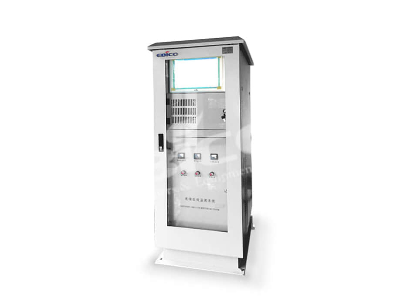

| Quantity: | |
|---|---|


Product Introduction
The Industrial Burner Online Monitoring System gives operators a clearer view of burner status and operating data from a centralized interface. Built around the requirements of each combustion project, it supports routine supervision, faster fault investigation, maintenance planning, and long-term performance review without replacing the burner’s dedicated safety controls.
Industrial combustion equipment produces operating information across burner controls, fuel systems, air systems, flame supervision devices, and process instruments. When these signals are viewed separately, operators may need more time to understand what happened before a shutdown or performance change.
The online monitoring system brings selected information into a structured interface. Operators can review current status, follow operating trends, and compare related signals without moving between multiple local devices.
Monitoring scope is defined for each project according to the burner configuration, available field signals, plant requirements, and permitted system access.
The system is designed to make burner information easier to interpret during daily operation and maintenance.
Authorized users can view selected burner and auxiliary-equipment conditions from the monitoring interface. The displayed information may include operating mode, sequence status, equipment feedback, process values, and event indications when these signals are available from the connected control system.
Recorded operating data helps engineers examine how selected values changed over time. Trend review can support fault investigation, commissioning checks, maintenance decisions, and comparison between different operating periods.
A timestamped event sequence can provide useful context when analyzing burner trips or abnormal conditions. The available event detail depends on the signals and records supplied by the site control architecture.
Each burner installation has a different fuel arrangement, control philosophy, instrument list, and operating responsibility. For that reason, monitored points are selected during system engineering rather than assumed from a fixed template.
Typical project data may include:
Burner run, standby, and stop status
Start-up and shutdown sequence stages
Flame presence or flame-failure indication
Fuel valve command and feedback
Fan or motor operating feedback
Air and fuel pressure measurements
Process temperature measurements
Damper or actuator position
Burner firing-rate indication
Alarm and trip status
Operating hours and start counts
Only signals supported by the installed instruments and control system can be displayed. Final point lists, data ranges, units, and update requirements should be agreed before configuration.
The monitoring system is arranged around the existing burner and plant control environment. Available operating signals are collected, processed, and presented through an operator-facing interface.
A typical project may include:
Field instruments and burner devices
Burner or combustion control equipment
Data collection and communication components
Monitoring software and data storage
Authorized operator or engineering access
The final architecture depends on the number of burners, site network conditions, existing automation equipment, cybersecurity policy, and required access locations.
Monitoring does not automatically mean remote burner control. Any command or control function must be separately engineered, risk-assessed, authorized, and protected within the plant’s approved control philosophy.
Burner faults often involve several conditions occurring within a short period. A single alarm may identify the final trip but not explain the events that led to it.
By reviewing related status changes and operating trends, maintenance teams can build a clearer timeline. This can help them decide whether to inspect an instrument, valve, actuator, fuel condition, airflow component, flame signal, or control sequence first.
The system supports diagnosis by organizing available data. It does not replace on-site inspection, qualified technical judgment, or the burner manufacturer’s prescribed safety checks.
Routine maintenance is more effective when technicians can combine scheduled service intervals with actual operating information.
Operating hours, start frequency, event history, and recurring deviations may help maintenance teams:
Prepare inspections before planned shutdowns
Identify frequently recurring operating issues
Prioritize checks on heavily used components
Compare conditions before and after service
Keep a clearer record of burner behavior
Provide relevant information to service engineers
Maintenance intervals and replacement decisions must still follow the applicable equipment manuals, site procedures, and inspection findings.
Historical trends can help plant teams understand whether the burner is operating consistently under comparable load and process conditions.
Engineers may review selected air, fuel, temperature, pressure, actuator, and firing-rate data where the relevant instruments are installed. This information can support combustion assessment and tuning preparation.
Monitoring data alone should not be treated as proof of combustion efficiency or emissions compliance. Confirmed conclusions require suitable calibrated instruments, defined test methods, and qualified combustion analysis.
The online monitoring system can be planned for a new burner project or evaluated as part of an upgrade to an existing installation.
For new systems, the monitoring requirements can be coordinated with the burner controls, field instruments, electrical design, network layout, and commissioning plan from the beginning of the project.
Retrofit feasibility depends on the available controller data, instrument outputs, panel space, documentation, communication capability, and site access rules. A site assessment may be required before the final scope is defined.
Where several burners are involved, the interface can be organized to help operators identify equipment by unit, area, process line, or operating status. The number of connected units and data-retention requirements must be established during engineering.
The system is intended for industrial combustion installations where operators and maintenance teams need structured access to burner operating information.
Typical application environments include:
Industrial boiler plants
Process heating systems
Thermal oil systems
Drying and curing lines
Industrial furnaces
Asphalt production facilities
Multi-burner process installations
Centralized energy and utility plants
Suitability depends on the burner system, installed controls, available instrumentation, operating environment, and project-specific monitoring objectives.
A reliable monitoring project begins with a defined list of equipment, signals, users, and operating responsibilities.
Before configuration, the project team should confirm:
Burner quantity and equipment identification
Existing control-system type
Available analog and digital signals
Required values, states, alarms, and trends
Historical data-retention needs
User roles and access permissions
Local and remote access requirements
Plant network and cybersecurity rules
Interface language and engineering units
Testing and acceptance criteria
During commissioning, displayed values should be checked against field conditions and source-system data. Event timestamps, units, ranges, equipment names, and user permissions should also be verified before handover.
The online monitoring system provides information for operating and maintenance decisions. It is not a substitute for the burner management system, flame safeguard, safety interlocks, emergency shutdown devices, or plant operating procedures.
Safety-related functions must remain within the approved safety and burner control architecture. Installation, modification, testing, and commissioning should be carried out by qualified personnel familiar with the connected combustion equipment.
Multi-burner or multi-area monitoring may be possible, but the final arrangement depends on network connectivity, controller compatibility, data volume, access permissions, and the required interface structure.
A retrofit may be possible when the existing controls provide suitable signals or communication access. Controller details, wiring drawings, instrument lists, and site network requirements should be reviewed first.
The effect depends on the selected architecture and data-storage arrangement. Local burner safety and control functions must continue independently of the monitoring connection. Data buffering and reconnection behavior should be defined during engineering.
Monitoring access does not automatically include remote control. Remote commands require a separate control design, authorization process, risk assessment, interlock review, and cybersecurity approval.
User access should be assigned according to plant responsibilities. Operator, maintenance, engineering, and administrative permissions can be defined during system configuration, subject to the selected platform and site policy.
Retention time depends on the number of recorded points, sampling frequency, storage capacity, reporting needs, and plant policy. These requirements should be agreed before the system is configured.
It can organize relevant operating data when suitable instruments are installed, but accurate efficiency calculation requires verified fuel, airflow, flue-gas, temperature, and load data. The required method and instrumentation must be defined for the project.
Provide the burner quantity, fuel types, control-system details, available drawings, instrument list, required monitoring points, access locations, data-retention period, network conditions, and any reporting or integration requirements.
Product Advantage
1. WIFl uploading of monitoring requirements
2. Unattended Remote monitoring
3. Plug-in probe with multi-door design
4. Double-layer Cabinet
1. Particulate Matter Monitoring Sub-system
2. Flue gas parameter monitoring sub-system
3. Pollutant monitoring subsystem
4. Data acquisition and control system
5. Data processing and communication system
6. Intelligent monitoring system
Core Process
Equipment Distribution -> Real-time Monitoring -> Fault Alarm -> News Feed -> Historical Data -> Remote Diagnosis -> Parameter Adjustment -> Remote Maintenance -> Cloud Configuration
Technical Parameters
| Style | Mono Block Burner |
| Fuel | |
| Type | Standard Burner |
Contact Us
Share your burner quantity, control-system details, available signals, network conditions, and monitoring goals. Our engineering team will help define a practical online monitoring scope for your installation.


