

Views: 0 Author: Site Editor Publish Time: 2026-08-11 Origin: Site
Selecting a new combustion system is never a simple component swap. It represents a critical capital decision. Your choice directly dictates fuel operational expenses. It also impacts emissions compliance and facility uptime. Many operations still rely on outdated mechanical linkages. Others struggle daily using undersized equipment. These engineering oversights result in hidden fuel waste. They also cause premature equipment wear and unexpected downtime. We want to transform how you evaluate this upgrade. This guide establishes a transparent, evidence-oriented approach. We move entirely beyond basic definitions. You will learn the necessary engineering criteria. We provide actionable sizing rules of thumb and modern control evaluations. Proper knowledge ensures your system operates smoothly. By the end, you will possess the actionable insights needed. You can confidently make a defensible, data-driven procurement decision.
Sizing Requires De-rating: A steam boiler burner must be sized higher than the boiler's output to account for efficiency losses (typically 85-95%) and ambient condition corrections (altitude/temperature).
Turndown Ratio Dictates Lifespan: Matching the burner's turndown ratio to facility load fluctuations prevents short-cycling and thermal stress.
Controls Drive ROI: Upgrading to linkageless (parallel positioning) controls with O₂ trim can yield a 2–4% reduction in fuel consumption, often paying for itself in under a year for high-capacity facilities.
Furnace Compatibility is Non-Negotiable: Flame geometry and backpressure tolerance must exactly match the boiler design to prevent tube rupture and backfiring.
Engineers often make a critical mistake during procurement. They match the burner input exactly to the boiler output. This approach completely ignores thermodynamics. Boiler efficiency never actually reaches 100%. Heat constantly escapes through the exhaust stack. Radiation loss occurs through the boiler shell. Therefore, your combustion input must always exceed the desired output.
You must calculate the efficiency gap. We use a standard engineering formula: Qinput = Qboiler / ηboiler. If your facility requires 10 MW of heat and your boiler operates at 85% efficiency, you need nearly 11.8 MW of input power. Sizing a steam boiler burner properly demands careful attention to these thermodynamic realities.
We rely on established engineering rules of thumb for baseline estimations. Use these quick conversion steps when evaluating initial sizing:
Identify your peak steam production requirement in tons per hour.
Multiply the tonnage by 700 kW. One ton per hour of steam production requires approximately 700 kW of boiler capacity.
Divide this number by your expected boiler efficiency percentage.
Add a 10% safety margin for unexpected peak loads.
Ambient conditions heavily influence capacity. Altitude and ambient air temperature decrease air density. Thinner air impacts the mass flow rate of combustion air. Standard reference conditions assume 20°C and 1.325 bar. You must apply an atmospheric correction factor if your plant sits above sea level. Failing to derate the equipment results in an undersized, fuel-rich, and non-compliant system at higher elevations.
Elevation (Meters) | Approximate Air Density (kg/m³) | Required Derating Factor |
|---|---|---|
Sea Level (0m) | 1.225 | 1.00 (No Derating) |
1,000m | 1.112 | 0.89 |
2,000m | 1.006 | 0.82 |
3,000m | 0.909 | 0.74 |
Combustion does not happen in a vacuum. It happens inside a highly pressurized metal box. The boiler burner must overcome the specific aerodynamic resistance of the furnace. We call this backpressure. Positive pressure furnaces create significant pushback. They require high static pressure forced-draft fans to punch the air through the chamber. Negative draft systems pull air through instead. You must match the fan specifications to the exact draft compatibility of your vessel.
Flame geometry determines tube integrity. The physical constraints of combustion are absolute. The flame shape must mirror the combustion chamber exactly. Imagine a steam boiler burner producing a long, narrow flame. If you install it in a short, wide combustion chamber, disaster strikes. The flame directly impinges on the rear water tubes. This creates localized boiling inside the pipes. Metal fatigue develops rapidly. Eventual catastrophic failure becomes inevitable.
Liquid fuels complicate mechanics further. Natural gas flows easily, but oil requires intense preparation. Dual-fuel or heavy oil setups rely on precise atomization. You have two main choices:
Mechanical Atomization: Uses high fluid pressure to push oil through a tiny nozzle. It works well for lighter oils and smaller capacities.
Medium Atomization: Injects steam or compressed air to shear the oil into microscopic droplets. It handles heavy, viscous fuels excellently.
Keep in mind that capacities over 2MW generally require dedicated pumping and heating sets. Cold heavy oil simply will not burn efficiently.
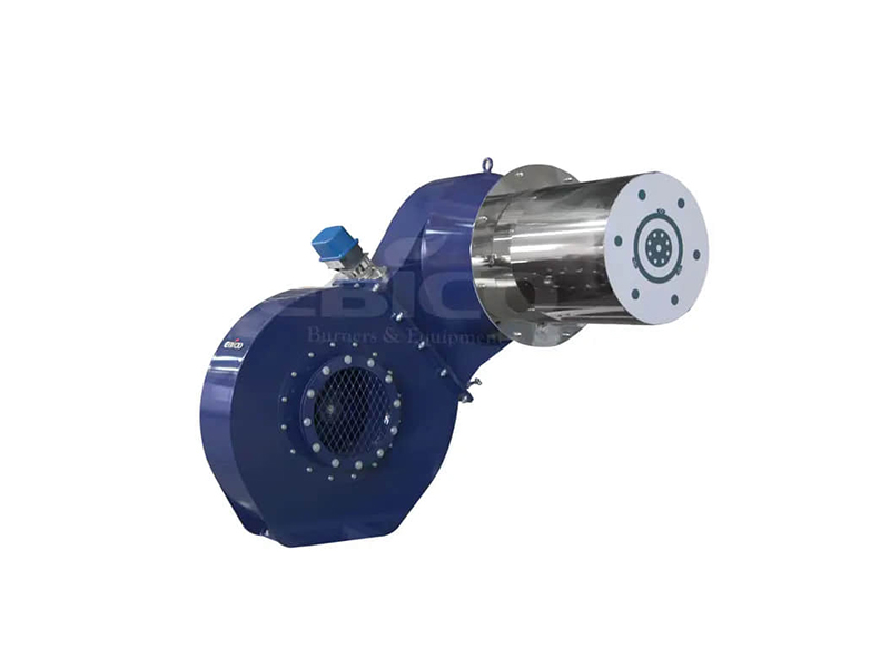
Your control strategy dictates your operational lifespan. The primary metric here is the turndown ratio. Turndown represents the ratio of maximum to minimum firing rates. A 10:1 ratio means the system can operate steadily at 10% of its maximum capacity. Facilities with highly variable steam loads desperately need high-turndown systems. Fully modulating controls adjust seamlessly to changing demands. They avoid the mechanical wear associated with basic step-fired models. On/off or high/low systems constantly purge the chamber. Every purge cycle blows valuable heat straight up the stack.
Legacy systems rely on mechanical linkages. A single motor uses physical metal rods and cams to move both the air damper and the fuel valve. Over time, these joints wear out. They create physical slop. Engineers call this hysteresis. Hysteresis leads to highly unpredictable air-to-fuel ratios. You tune the system on Monday, but by Friday, it drifts. It either wastes fuel or produces dangerous soot.
We highly recommend eliminating hysteresis entirely. Linkageless systems provide a massive advantage. They utilize independent servomotors equipped with parallel positioning software. One motor drives the air. Another motor drives the fuel. A microprocessor synchronizes them perfectly across the entire firing curve. Linkageless technology represents the modern standard for precise, repeatable combustion control.
Feature | Mechanical Linkage | Linkageless (Parallel Positioning) |
|---|---|---|
Actuation Method | Single motor with physical rods | Independent, software-driven servos |
Hysteresis Risk | High (joints wear out quickly) | Zero (no physical rods to wear) |
Tuning Precision | Poor (drifts over time) | Excellent (repeatable accuracy) |
Turndown Capability | Limited (often 4:1 max) | High (up to 10:1 or more) |
Combustion is a delicate chemical balancing act. Stoichiometric combustion represents the perfect mix of fuel and oxygen. In a laboratory, every molecule burns perfectly. However, stoichiometric combustion remains physically impossible in harsh industrial settings. Variations in fuel pressure and air temperature constantly disrupt the mix. You must introduce excess air to guarantee complete combustion.
You must follow a strict rule of thumb. Every 1% of excess O₂ beyond the optimum level wastes approximately 1% of your fuel. The fan blows cold air into the chamber. The flame heats that air, and the heat escapes out the chimney. Conversely, running the mix too rich produces deadly carbon monoxide. It also coats the boiler tubes in soot. Soot acts as a powerful insulator, destroying heat transfer rates.
Automatic O₂ trim systems solve this balancing act. They utilize sensitive zirconia sensors installed directly in the exhaust stack. These sensors read oxygen levels in real time. They send data back to a central controller. The controller adjusts a Variable Frequency Drive (VFD) connected to the combustion fan. It instantly corrects the air flow. It maintains the perfect ratio regardless of atmospheric changes.
The financial justification for these systems is undeniable. Standard Department of Energy (DOE) guidance strongly advocates for their use. For high-capacity steam boilers, O₂ trim systems typically save 2-4% on annual fuel costs. This creates a rapid return on investment. Upgrading a high-capacity Boiler Burner with O₂ trim often pays for itself in under a single year. The fuel savings easily justify the higher initial CapEx.
Strict local environmental regulations increasingly dictate equipment selection. You must secure firm emissions guarantees before making a purchase. Low-NOx performance is no longer optional. Flue Gas Recirculation (FGR) serves as the standard mechanism for achieving Ultra-Low NOx emissions. FGR pipes a portion of the exhaust gas back into the combustion zone. This lowers the peak flame temperature. Lower temperatures prevent nitrogen from binding with oxygen. However, we must warn you about FGR drawbacks. It reduces overall efficiency. It also requires careful fan sizing, as the fan must handle a significantly larger volume of gas.
Safety integration protects your facility and your personnel. A robust Burner Management System (BMS) acts as the brain of your safety protocol. The BMS handles pre-ignition purging, pilot lighting, and main flame establishment. It demands specific hardware integrations:
Dual Safety Shut-off Valves: These prevent explosive fuel accumulation during off cycles. If one valve leaks, the second blocks the flow.
Dual UV/IR Flame Scanners: These optical sensors monitor the flame constantly. If the flame drops out, they shut the fuel valves in milliseconds.
High/Low Gas Pressure Switches: These prevent ignition if the fuel supply line fluctuates outside safe operational parameters.
Procurement due diligence extends far beyond the spec sheet. You must verify vendor credentials and prioritize maintenance access. Look for smart physical designs. Hinged housings allow technicians to swing the unit open easily. They can perform routine nozzle inspections without executing a full, heavy removal. Finally, the industrial market suffers from counterfeit equipment. Untested copycats pose massive explosion risks. Always demand authentic documentation. Verify OEM QR codes and cross-reference serial numbers directly with the manufacturer before accepting delivery.
Audit Your Baseline: Procurement and engineering teams must record current baseline efficiency metrics and emissions outputs before exploring new equipment.
Map Steam Loads: Carefully graph your peak versus off-peak steam demands to determine the precise turndown ratio your facility requires.
Prioritize Smart Controls: Recognize that linkageless servos and O₂ trim systems offer the fastest payback periods through sustained fuel reductions.
Demand Vendor Guarantees: Require guaranteed emissions curves and efficiency charts from vendors prior to issuing any purchase orders.
A: It depends on load variance, but 8:1 to 10:1 is standard for variable industrial loads to prevent short-cycling.
A: Thinner air at high altitudes reduces oxygen mass per cubic foot, requiring larger forced draft fans and a capacity correction factor to maintain the required output.
A: Yes, retrofitting is common and highly cost-effective, provided the new burner's flame geometry and backpressure capabilities match the legacy furnace design.
A: Mechanical linkages use a single motor and physical rods to move air and fuel valves, prone to wear and inaccuracy. Linkageless systems use independent, software-controlled servo motors for highly precise, drift-free positioning.
