

Views: 0 Author: Site Editor Publish Time: 2026-09-07 Origin: Site
Reducing combustion temperatures effectively lowers NOx emissions. However, this action inherently risks raising Carbon Monoxide (CO) and decreasing overall fuel efficiency. This inverse relationship creates a fundamental combustion dilemma for industrial operators. Facility managers and engineers understand this challenge deeply. Tuning is not just a routine maintenance task. It serves as a critical compliance and operational threshold. Striking the right balance requires highly precise control mechanisms. Evaluating mechanical design and control systems before procurement dictates long-term success. It determines the stability and cost-effectiveness of all future tuning efforts. You will learn how to navigate the physics of emissions, manage critical tuning parameters, and select the right burner technology for stable operation.
The NOx-CO tradeoff requires precise management of flame temperature, excess air, and residence time; lowering one emission often spikes the other.
Reliable tuning relies on advanced control strategies, such as linkage-less controls and precise Flue Gas Recirculation (FGR) metering.
Not all burners handle load swings equally; evaluating turndown ratio and flame stability is critical to avoiding CO spikes during low-load operation.
Shortlisting an Ultra Low Emission Burner requires matching the technology to site-specific variables, including furnace geometry, draft conditions, and fuel composition.
High peak flame temperatures produce thermal NOx. The nitrogen and oxygen in combustion air react aggressively under extreme heat. Artificially cooling the flame reduces this chemical reaction. Operators use Flue Gas Recirculation (FGR) or excess air to achieve this cooling effect. However, excessive cooling causes incomplete combustion within the furnace. Incomplete combustion inevitably produces Carbon Monoxide. Lowering one emission often spikes the other. This inverse relationship forms the core challenge of burner tuning. Thermal NOx depends exponentially on temperature and linearly on time. CO formation represents unburned fuel. Unburned fuel equates directly to lost boiler efficiency and wasted thermal energy.
Poor emission balancing brings high stakes. You might fail strict environmental emissions audits. High excess air wastes valuable fuel by sending usable heat straight up the stack. Flame instability causes forced downtime and trips the boiler off-line. These operational issues drain budgets rapidly. They also invite severe legal penalties from local environmental agencies. Facilities operating in strict regulatory zones cannot afford sloppy tuning. Consistent compliance requires precision engineering rather than guesswork.
Older combustion systems rely heavily on mechanical linkages. These metal arms connect the air damper and fuel valve to a single positioning motor. Over time, these mechanical parts suffer from hysteresis. Daily wear and tear cause them to stick or slip during operation. This mechanical slop makes precise, repeatable tuning nearly impossible across the entire firing range. You cannot maintain a tight compliance window using outdated linkage controls. Upgrading to digital control systems becomes a functional necessity for compliance.
Continuous O2 monitoring is vital for emission control. It allows the control panel to dynamically adjust the air-to-fuel ratio. This active adjustment keeps the system squarely in the narrow compliance window. O2 trim systems respond instantly to ambient air density changes. They prevent the burner from drifting out of tune when weather patterns shift. Maintaining optimal O2 levels prevents both CO formation and wasted fuel. Modern sensors use zirconium oxide probes to measure oxygen content directly in the exhaust stream. Fast sensor response times ensure the burner reacts instantly to load changes.
FGR introduces inert flue gas back into the combustion zone. The recycled gas absorbs thermal energy and lowers peak flame temperatures. You must evaluate FGR valve precision carefully during the tuning process. Introducing too much FGR quenches the flame entirely. Flame quenching immediately spikes CO levels to unacceptable regulatory ranges. Precision metering valves offer the fine control needed to balance this thermal absorption. Proper FGR ducting design prevents condensation issues and ensures a steady flow of inert gas to the burner head.
Staged combustion separates the mixing process into distinct physical zones. You introduce fuel and air at different stages within the combustion chamber. This technique creates a cooler, elongated flame shape. It intentionally avoids the intense hot spots where thermal NOx forms rapidly. Staging requires sophisticated mechanical design for optimal mixing. A well-staged flame burns cleanly without generating excess Carbon Monoxide. Engineers must calibrate the primary and secondary air zones perfectly. This calibration prevents rich fuel pockets from escaping the primary combustion zone unburned.
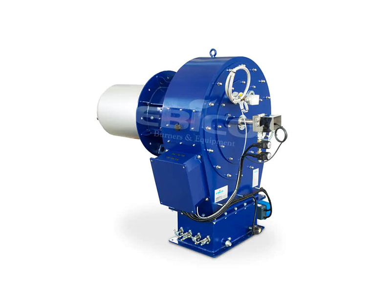
Modern combustion systems demand advanced digital controls. Single-point positioning uses one motor to move both fuel and air valves simultaneously. Parallel positioning uses independent servo motors for each component. Linkage-less controls allow independent, repeatable positioning at every load point along the combustion curve. Reliable tuning demands this modern, decoupled architecture. Parallel positioning systems integrate seamlessly with Variable Frequency Drives (VFDs). VFDs control the blower motor speed precisely. This reduces electrical consumption and improves air flow accuracy during low fire conditions.
Control System Positioning Comparison
Feature | Single-Point Positioning (Legacy) | Parallel Positioning (Modern) |
|---|---|---|
Mechanical Setup | Single motor driving complex linkages | Independent servo motors for each valve |
Tuning Precision | Low; prone to hysteresis and slipping | High; pinpoint accuracy across all loads |
Repeatability | Degrades over time due to mechanical wear | Remains constant via digital setpoints |
VFD Integration | Difficult; often requires external controls | Native; easily maps blower speed to load |
Turndown measures true operational flexibility. It defines how well an Ultra Low Emission Burner maintains balance at low firing rates. A high turndown ratio prevents the burner from constantly cycling on and off. Cycling causes severe purge-cycle heat losses. It also triggers significant low-load CO spikes as the flame establishes itself. Continuous low-fire operation stabilizes emissions and saves energy. Evaluating turndown capabilities prevents operational headaches during low-demand seasons. Superior turndown limits thermal shock to the boiler vessel by maintaining a steady, low flame.
Physical design dictates your baseline emissions profile entirely. You might select surface-stabilized, premix, or staged combustion heads. The internal geometry defines how well gases mix before tuning even begins. A poorly designed head cannot be magically tuned into compliance. Engineers utilize complex swirlers and diffusers to manage air velocity. The shape of the firing head influences flame retention and stability. Selecting the correct geometry ensures a solid foundation for field tuning.
Flame Instability and Rumble: Chasing single-digit NOx numbers presents immediate physical dangers. Operators sometimes push excess air or FGR too high to meet strict targets. This aggressive over-cooling causes destructive acoustic vibrations, commonly known as rumble. Severe rumble damages boiler refractory materials over time. It can also cause a complete loss of flame, forcing an emergency boiler shutdown.
Furnace Geometry Conflicts: A combustion system relies heavily on its containing vessel. Mismatched furnace geometry creates massive, unresolvable problems. If the flame touches cold boiler tubes, it instantly quenches. Flame impingement generates massive Carbon Monoxide immediately. Tuning parameters cannot fix impingement caused by an oversized or poorly shaped flame.
Varying Environmental Variables: The surrounding environment constantly changes. Ambient air temperatures fluctuate significantly from morning to night. Barometric pressures shift dramatically with passing weather fronts. Natural gas BTU values vary depending on the pipeline supply. A perfectly tuned system easily falls out of compliance without dynamic trim capabilities to adjust for these shifts.
Improper Fuel Blending: Facilities increasingly utilize mixed fuel strategies. Combining natural gas with hydrogen or biogas introduces combustion volatility. Hydrogen burns hotter and faster than methane. This increases thermal NOx production rapidly. Tuning must account for variations in fuel composition to prevent sudden emission spikes.
Conducting a Baseline Audit: Start by gathering hard empirical data. Record your current emissions output across all firing rates. Measure draft variations across the entire load profile. Document the operational limits of your existing forced draft fans. Establish clear performance targets before ever contacting equipment vendors.
Evaluating Vendor Guarantees: Scrutinize all performance guarantees closely. Do not accept a guarantee only valid at high fire. Ensure the vendor guarantees simultaneous NOx and CO levels across the entire operating range. Ask explicitly how a Low NOx Burner performs at 20 percent load. Demand documented proof from similar installations.
Analyzing Draft and Pressure Conditions: Assess your site-specific draft conditions carefully. High FGR rates require powerful blower motors to overcome resistance. Ensure your existing fan infrastructure can handle the increased static pressure. Undersized blowers restrict air flow and cause rich combustion mixtures.
Next Steps and Engineering Reviews: Engage closely with applications engineers early in the process. Request detailed Computational Fluid Dynamics (CFD) modeling for complex applications. Ask for a site-specific engineering review. This ensures the proposed equipment matches your actual boiler dimensions perfectly. CFD modeling predicts flame shape and temperature distribution before installation begins.
Balancing NOx and CO requires engineered precision. It is never a guessing game for facility operators. Success relies on optimal burner geometry paired directly with advanced digital controls. High turndown ratios and parallel positioning systems provide the necessary tuning flexibility. Choosing the cheapest initial equipment often backfires. It costs facilities heavily in ongoing fuel penalties and endless tuning labor. Do not wait for a failed emissions test to take action. Schedule a comprehensive emissions audit today. Consult an experienced combustion engineer immediately. Evaluate your current system for strategic retrofit or replacement options to ensure long-term operational stability and environmental compliance.
A: Industry compliance targets typically require CO levels to remain under 50 ppm. However, local regulations dictate the exact ceiling. Some strict air quality districts mandate CO limits as low as 10 ppm. Always consult your specific environmental permit to confirm your legal threshold before starting the tuning process.
A: High CO at low fire usually stems from a poor turndown ratio. As the firing rate drops, mixing energy decreases rapidly. Fuel and air no longer blend optimally. Additionally, excessive FGR rates at low loads can over-cool the flame, leading to incomplete combustion and sudden CO spikes.
A: O2 trim systems automatically compensate for ambient changes like temperature and humidity. They maintain the specified air-to-fuel ratio perfectly. However, they rely entirely on the baseline combustion curve established during tuning. If mechanical linkages slip or burner geometry degrades, O2 trim alone cannot prevent emissions drift.
