

Views: 0 Author: Site Editor Publish Time: 2026-11-09 Origin: Site


Operating a dual fuel system requires highly precise combustion management. A single compromised air-fuel setting wastes energy. It creates dangerous soot. It also introduces significant safety risks during rapid fuel changeovers. Plant managers and facility engineers evaluating burner upgrades must clearly understand modern control capabilities. Modern Burner Management Systems (BMS) handle the distinctly different stoichiometric requirements of natural gas and fuel oil effortlessly. They prevent operational instability when you switch fuel sources under load.
Examining how precise, independent air-fuel curves are mapped provides a highly practical framework. You will discover exactly how to select systems ensuring safe, compliant, and efficient operation across both fuels. We will explore the physical imperatives driving these distinct curves. We will compare linkageless controls against traditional methods. Finally, we detail best practices for safe commissioning. You will learn how proper baseline establishment and multi-point interpolation secure peak boiler efficiency.
Independent Mapping is Mandatory: Gas and oil possess different volumetric, viscosity, and combustion characteristics, requiring entirely distinct air-fuel ratio profiles.
Linkageless Control Wins for Accuracy: Modern parallel positioning (linkageless) systems utilize independent servomotors, eliminating the mechanical hysteresis and compromises of traditional single-point jackshafts.
Safety Dictates the Sequence: Proper curve setting must integrate cross-limiting control to ensure safe oxygen levels during load changes, preventing fuel-rich scenarios.
O2 Trim Adapts the Curve: Real-world variables (temperature, humidity) require continuous, independent O2 trim adjustments for each specific fuel mode.
Attempting to force both fuels onto a single mechanical cam curve inevitably leads to operational compromises. Engineers often face severe challenges when utilizing single-profile systems. You typically see excessive air levels when burning gas. Alternatively, you experience heavy sooting when operating on oil. These compromises degrade heat transfer efficiency and accelerate equipment wear.
Combustion reality dictates completely different physical approaches for liquid and gaseous fuels. Natural gas demands roughly a 10:1 air-to-fuel ratio by volume. Methane mixes readily with combustion air. It burns cleanly using much lower excess air. Conversely, fuel oil, such as #2 diesel, requires physical atomization. It demands higher excess air, particularly at low fire. This extra air helps break the liquid into combustible droplets. It ensures complete mixing and prevents carbon buildup on boiler tubes.
Furthermore, an Oil and Gas Burner typically exhibits different turndown capabilities for each fuel. Natural gas often allows a wider modulation range. Liquid fuels may destabilize or lose atomization pressure at very low firing rates. Control systems must accommodate a wider turndown for gas. They must do so without stalling the flame when the system operates on oil. Independent mapping solves this physical discrepancy entirely.
Combustion Profile Comparison Chart
Fuel Type | Physical State | Typical Excess Air Target | Atomization Required? | Turndown Capability |
|---|---|---|---|---|
Natural Gas | Gaseous | 10% - 15% | No | High (often 10:1 or more) |
Fuel Oil (#2) | Liquid | 15% - 25% | Yes | Moderate (often 4:1 to 8:1) |
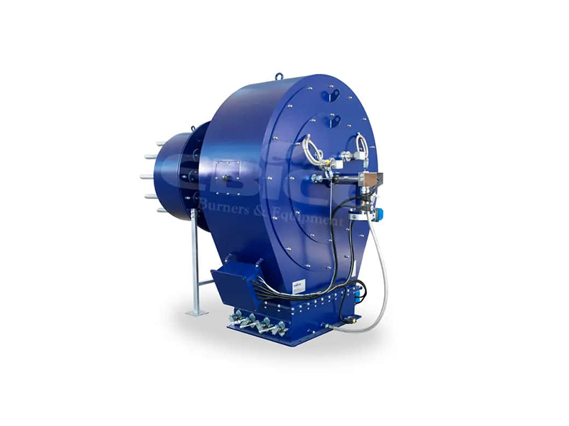
When evaluating a Dual Fuel Boiler Burner upgrade, the method of ratio control forms the primary differentiator. Facility managers must choose between legacy mechanical systems and modern digital platforms. The right choice eliminates drift and ensures repeatable combustion profiles.
Traditional jackshafts represent the legacy approach to combustion control. This method relies heavily on physical linkages connecting a single drive motor to the air damper and fuel valves. The implementation risks remain high. Hysteresis, or mechanical slop in the linkage, causes significant drift over time. Thermal expansion of metal connecting rods alters the valve positions slightly as the boiler heats up. This requires mechanical tuning compromises. Technicians must adjust the cams to a "middle ground" setting. This middle ground satisfies neither fuel perfectly.
Parallel positioning, often called linkageless control, represents the modern industrial standard. It resolves mechanical limitations through digital precision.
Independent Actuation: The system utilizes highly precise actuators, known as servomotors. They control the air damper, gas valve, and oil valve entirely separately.
High-Resolution Positioning: Modern servomotors adjust to within 0.1 degrees of accuracy. They eliminate mechanical hysteresis entirely.
Digital Storage: The feature-to-outcome benefit is massive. A Programmable Logic Controller (PLC) or BMS stores multiple, completely independent electronic profiles.
Seamless Changeovers: Switching fuels requires a simple digital command. It does not require any mechanical adjustment or physical pin changes.
This digital independence allows you to optimize gas for maximum efficiency while tuning oil for maximum stability. You never sacrifice one for the other.
Understanding how an application engineer maps a Dual Fuel Burner in a linkageless system demystifies the commissioning process. Proper setup guarantees reliable light-offs and clean high-fire operation.
Engineers begin by establishing the baseline at low and high fire. They conduct independent settings of the low-fire ignition point. You must ensure a smooth, quiet light-off for gas first. Next, engineers address the distinctly heavier demands of oil atomization. Oil requires more air at ignition to prevent smoking. Once low fire stabilizes, technicians set the high-fire limits. They base these upper limits on maximum stack temperature, boiler capacity rating, and strict local emissions targets.
After establishing the boundaries, the multi-point curve interpolation process begins. The engineer sets intermediate points to guide the burner through its entire modulation range.
Analyze Combustion Variables: The technician connects an exhaust gas analyzer to monitor O2, CO, and NOx levels continuously.
Map Specific Load Points: Standard practice requires mapping 10 to 24 specific load points between low and high fire. You must map these points separately for *each* fuel.
Adjust Air and Fuel Independently: At each designated point (e.g., 20% load, 30% load), the technician manually adjusts the servomotors. They achieve the perfect stoichiometric ratio for that exact firing rate.
Save to BMS Memory: The controller memorizes the exact rotational position of all servomotors at that specific load point.
Enable Controller Algorithms: The advanced controller algorithm interpolates smoothly between these established points.
This strict interpolation ensures the servomotors move in perfect lockstep during continuous load transitions. It effectively prevents transient fuel-rich conditions that cause soot or vibrations.
Viewing combustion through a compliance and security lens reveals why standard PID control fails industrial requirements. Standard PID logic only looks at pressure or temperature setpoints. It does not natively verify safe air-fuel mixtures. National Fire Protection Association (NFPA) guidelines require specific safety logic during modulation.
The cross-limiting principle, also known as lead/lag control, provides this required safety layer. It ensures the boiler never enters a dangerous fuel-rich state during rapid load swings. When a sudden demand for steam occurs, the burner must modulate up. When demand drops, it must modulate down quickly.
During an increasing load scenario, the system must command the air damper to open *before* the fuel valve opens. We call this "Air leads." The extra air guarantees enough oxygen exists to burn the incoming surge of fuel. During a decreasing load scenario, the system must command the fuel valve to close *before* the air damper closes. We call this "Fuel leads." The air damper remains open slightly longer to clear remaining fuel.
Cross-Limiting Sequence Actions
Load Transition | Primary Action (Lead) | Secondary Action (Lag) | Safety Outcome |
|---|---|---|---|
Increasing Demand (Modulating Up) | Air damper opens to new setpoint | Fuel valve opens to match air | Prevents fuel-rich explosion risks |
Decreasing Demand (Modulating Down) | Fuel valve closes to new setpoint | Air damper closes to match fuel | Prevents unburned fuel accumulation |
Any shortlisted BMS must possess built-in, hard-coded cross-limiting capabilities. It must apply these rules to both gas and oil profiles independently. You cannot rely on simple timers. The system must verify actuator feedback positions continuously.
Even the most perfectly commissioned air-fuel curve degrades over time. A static curve remains highly vulnerable to real-world environmental shifts. Seasonal changes in barometric pressure and air density alter the actual mass of oxygen entering the burner. Fuel calorific value fluctuates. Mechanical wear subtly changes fan performance. Continuous tuning becomes essential.
How O2 trim works in dual mode represents the pinnacle of modern efficiency. An exhaust gas analyzer, typically utilizing a zirconium oxide sensor, sits in the boiler stack. It feeds real-time oxygen data back to the central controller. The BMS compares this live reading against the saved baseline curve.
A crucial feature of advanced systems is setpoint separation. The BMS must store *separate* O2 target setpoints for gas and oil. Natural gas might operate perfectly targeting 3% O2 across the mid-range. However, switching to oil might require targeting 4.5% O2 to prevent soot. A smart trim system automatically shifts its target when the operator switches fuel modes.
The success criteria for this advanced tuning are highly measurable. It reduces annual fuel consumption by 2-5%. It tightly controls excess air, keeping heated air from escaping up the stack unnecessarily. Furthermore, it prevents unexpected emissions compliance violations. By holding O2 levels constant, it stabilizes NOx and CO production. This continuous, automated correction validates the initial capital expenditure of the advanced controller.
Properly setting air-fuel curves for dual fuel operations requires abandoning mechanical compromises. Facility operators must pivot in favor of electronic, linkageless control systems. Attempting to manage natural gas and fuel oil on a single physical linkage guarantees inefficiency and increases safety risks.
Facility managers should actively audit their current linkage systems for hysteresis and drift. You must evaluate modern BMS solutions that offer independent multi-point mapping. Prioritize systems featuring hard-coded cross-limiting logic and dual-profile O2 trim capabilities. These features ensure combustion remains stable regardless of the active fuel source.
An upfront investment in precise combustion control minimizes downtime during critical fuel changeovers. It eliminates the manual tuning adjustments traditionally required. Ultimately, leveraging dedicated digital curves maximizes long-term boiler efficiency and secures robust operational safety.
A: It depends on the burner management system. Advanced systems support "on-the-fly" changeovers with automated purge and sequence logic. They map the transition digitally. Older mechanical systems require a manual shutdown, physical linkage adjustment, and a full restart sequence. Upgrading to a digital BMS enables seamless transitions without losing steam pressure.
A: For industrial linkageless systems, it is recommended to map between 10 and 24 points across the firing range for each fuel. This density ensures a smooth, highly accurate combustion profile. It allows the controller to interpolate positions perfectly, preventing fuel-rich pockets during rapid load modulations.
A: Fuel oil requires physical atomization to break the liquid into tiny droplets before combustion. Higher excess air helps ensure complete mixing with the fuel spray. It prevents unburned carbon from turning into soot. Soot quickly fouls boiler tubes, drastically reducing heat transfer efficiency and increasing maintenance demands.
A: Hysteresis refers to the mechanical "play" or looseness in physical linkages and jackshafts. It causes the air damper and fuel valves to land in slightly different positions depending on whether the burner is modulating up or down. This ruins the precise air-fuel ratio, causing wasteful excess air or dangerous fuel-rich conditions.
