

Views: 0 Author: Site Editor Publish Time: 2026-09-04 Origin: Site
Consistent gas pressure forms the bedrock of safe and efficient combustion in industrial facilities. Variations like sudden drops or unexpected spikes directly threaten operational stability. They severely shorten equipment lifespan and risk strict emissions compliance. Pressure issues rarely remain isolated burner problems. Instead, they act as severe system-level risks. These risks dictate fuel usage, compromise facility safety, and lower product quality during process heating.
We designed this comprehensive guide for facility managers and engineers. You might be evaluating vital burner upgrades right now. Perhaps you need to diagnose chronic combustion faults affecting production. Or maybe you are specifying new equipment for variable-pressure environments. A standard Natural Gas Burner relies entirely on predictable fuel delivery to function properly.
Here, you will learn exactly how pressure dynamics impact your industrial heating systems. We will explore everything from the physical dangers of under-firing to precise mitigation strategies. You will discover practical ways to protect your facility from the hidden costs of gas pressure volatility.
Efficiency & Output: Low pressure starves the flame, reducing thermal output, while high pressure causes over-firing and potential heat exchanger damage.
Safety & Compliance: Pressure fluctuations skew fuel-air ratios, leading to dangerous carbon monoxide (CO) spikes and violating NOx emission limits.
Equipment Selection: Modern modulating burners and properly sized gas trains are critical investments for facilities experiencing supply pressure volatility.
Implementation Reality: Burner performance depends on dynamic (running) pressure, not just static (standby) pressure.
Pressure instability creates immediate and measurable problems inside the combustion chamber. An industrial heating system operates on precise mathematical ratios. When the fuel supply fluctuates, the entire combustion equation breaks down. Facility managers must understand the physical symptoms of these variations to prevent catastrophic equipment failure.
Under-firing occurs when the gas supply fails to deliver adequate volume to the burner head. This creates two distinct operational hazards.
First, it causes severe flame instability and sooting. Reduced gas velocity at the burner head produces lazy, yellow flames. These unstable flames fail to mix properly with combustion air. The resulting incomplete combustion leads to rapid soot accumulation inside the heat exchanger. Heavy soot acts as an insulator. It blocks heat transfer and forces the system to work harder.
Second, under-firing guarantees capacity loss. A starved burner cannot meet the facility’s thermal demand. The system begins short-cycling as it struggles to reach the setpoint temperature. This continuous on-and-off cycling causes severe process delays. It also accelerates wear on igniters, relays, and blower motors.
Conversely, high pressure forces excessive fuel into the combustion zone. Over-firing presents acute safety and maintenance risks.
The primary concern is heat exchanger stress. Pushing excess BTUs beyond the system design capacity drastically accelerates metal fatigue. The metal expands rapidly under the intense heat. This thermal shock causes micro-fractures, eventually leading to complete structural failure. Replacing a cracked heat exchanger requires massive capital expenditure and prolonged facility downtime.
Furthermore, over-firing causes dangerously incomplete combustion. The system introduces excess fuel without a proportional increase in combustion air. This rich mixture generates dangerous levels of carbon monoxide (CO) and unburned hydrocarbons. These toxic gases pose immediate life-safety threats to facility personnel.
Many technicians fall into a common diagnostic trap. They measure pressure only when the system is offline. We must distinguish between static and dynamic pressure.
Static pressure is the baseline reading when no gas is flowing. A system might show standard static pressure, such as 7 to 14 inches of water column (in. w.c.). However, dynamic pressure represents the actual running condition. Facilities often experience severe dynamic drops when multiple burners ignite simultaneously. The main supply line simply cannot deliver the required volume. Evaluating dynamic pressure is the only accurate way to assess system health.
Operational Impact Comparison: Gas Pressure Deviations
Deviation Type | Primary Symptom | Equipment Risk | Safety Concern |
|---|---|---|---|
Low Pressure (Under-firing) | Lazy, yellow flame | Soot buildup, short-cycling | Delayed ignition, flame rollout |
High Pressure (Over-firing) | Lifting, noisy flame | Heat exchanger cracking | High Carbon Monoxide (CO) output |
Dynamic Drop | Intermittent shutdowns | Control board burnout | Nuisance tripping during peak loads |
Environmental regulations demand strict adherence to emission standards. Modern facilities utilize specialized combustion technology to meet these mandates. However, these advanced systems exhibit extreme sensitivity to fuel supply variations.
A Low NOx Gas Burner relies on highly precise fuel-air mixing to operate legally. Engineers design these units to keep flame temperatures below the NOx formation threshold. They often achieve this utilizing flue gas recirculation (FGR) or advanced lean-burn technologies. FGR introduces inert exhaust gas back into the combustion zone. This process absorbs heat and lowers the peak flame temperature. This delicate balance requires absolute fuel pressure stability.
Even minor pressure fluctuations disrupt this delicate ratio. An uncontrolled pressure spike enriches the mixture instantly. More fuel enters the chamber without corresponding air or FGR volume. This enrichment raises the peak flame temperature dramatically. The burner instantly pushes the system out of environmental compliance. In jurisdictions with continuous emissions monitoring systems (CEMS), this results in immediate fines. Drop-offs in pressure lean out the mixture too far. This causes the flame to blow off the burner head, triggering safety shutdowns.
When evaluating low-emission equipment, buyers must assess the sensitivity of the linked gas-air control systems. You must analyze this in the context of your facility gas supply stability.
Single-point linkage systems connect the gas valve and air damper physically. They cannot adapt to varying supply pressures. Conversely, parallel positioning systems use independent servo motors for gas and air. These digital systems monitor inputs continuously. They can make micro-adjustments to maintain the correct ratio even if minor pressure shifts occur. Facilities with known supply volatility must prioritize parallel positioning technology.
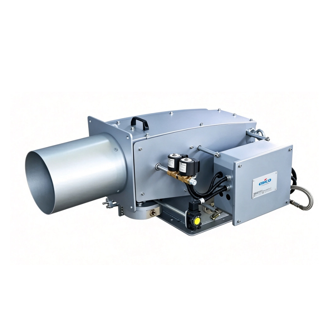
Standard steam boilers can sometimes absorb minor operational anomalies. Thermal fluid heating systems cannot. They represent high-stakes industrial applications where precision is mandatory.
Unlike standard boilers, thermal fluid systems utilize specialized synthetic oils as heat transfer mediums. These systems require exact, sustained heat transfer rates. If the heat flux becomes too intense, the thermal oil begins degrading. Industry experts refer to this degradation as "cracking." Cracked fluid forms solid carbon deposits inside the piping network. These deposits destroy pumping efficiency and ruin the costly thermal fluid.
A Gas Burner for Thermal Oil Heater must maintain absolute flame geometry stability. The flame must never touch the heater coils. Pressure variations alter the physical shape and length of the flame. A sudden pressure spike can elongate the flame, causing it to impinge directly on the tubing. This direct contact causes localized overheating, known as hot spots. Hot spots instantly crack the thermal fluid and compromise the structural integrity of the coils.
Standard combustion equipment falls short in these critical applications. Facilities must deploy advanced solutions to protect their thermal fluid investments.
High-Turndown Ratios: Burners must offer wide turndown capabilities (e.g., 10:1). This allows them to modulate output smoothly without shutting down during minor load changes.
Mass-Flow Sensors: Integrating thermal mass-flow meters provides real-time fuel density data. The burner controller uses this data to adjust the air damper instantaneously.
Fully Modulating Controls: These systems actively compensate for pressure shifts. They eliminate the rigid, stepped firing rates that shock thermal oil systems.
These features remain non-negotiable for thermal fluid applications. They actively prevent fluid degradation and ensure safe, continuous process heating.
A burner cannot outperform its upstream fuel supply. The hardware delivering the gas is just as important as the burner firing it. Proper evaluation requires a holistic view of the entire gas train assembly.
We must clarify that the burner is only as good as the gas train feeding it. The gas train regulates, measures, and secures the fuel flow. Main regulators must be correctly sized for both minimum and maximum flow rates. An oversized regulator cannot control low-fire flow accurately. This causes "droop" or hunting, where the gas pressure bounces erratically. An undersized regulator restricts volume, starving the burner at high-fire. Engineers must specify regulators based on exact flow characteristics, not just pipe diameter.
The type of burner control dictates how well the system handles pressure volatility. You have three primary categories to consider.
Single-stage Burners: These units are cheaper to purchase initially. However, they are highly vulnerable to pressure changes. They operate strictly at one fixed firing rate. If pressure drops, they fail.
Two-stage Burners: These offer a high and low fire position. They provide marginal improvement but still rely on fixed mechanical settings.
Fully Modulating Burners: These adjust the firing rate seamlessly across a wide curve. When paired with advanced servo motors, they can better handle minor supply inconsistencies. They match the exact thermal load requirement minute by minute.
Equipment protection relies on sensitive, fast-acting interlocks. Ensure the specified burner package includes high and low gas pressure switches (HGPS and LGPS). You must calibrate these switches to your specific dynamic pressure baseline. If supply pressure breaches the safe operating window, these switches trigger a safe shutdown. They stop combustion before conditions become dangerous. Regular testing of these switches is a mandatory safety practice.
Installing top-tier equipment means nothing without rigorous commissioning. Proper deployment bridges the gap between theoretical engineering and actual operational reliability.
You cannot tune a modern combustion system by eye. A natural gas burner must be tuned using a calibrated digital combustion analyzer. Technicians must perform this tuning under actual load conditions. They must check O2, CO2, and CO levels across the entire firing curve.
Establish Baseline Draft: Ensure the stack provides adequate draft before introducing fuel.
Set Low-Fire: Adjust the fuel-air mixture at minimum input to ensure stable ignition.
Map the Curve: Gradually increase the firing rate, recording analyzer data at every 10% increment.
Verify High-Fire: Confirm the system meets peak demand without exceeding CO or NOx thresholds.
This empirical tuning process guarantees the system operates safely regardless of minor environmental changes.
Installation errors routinely ruin burner performance. We frequently address common manifold design flaws in the field. Undersized piping creates severe friction loss, artificially lowering the pressure at the burner. Another common error involves placing regulators too close to the main burner valves. Gas needs straight pipe length to stabilize after passing through a regulator. Placing valves too close creates turbulence and false pressure readings. This turbulence causes erratic fuel-air mixing and flame instability.
Avoid rushing equipment procurement. We advise buyers to require a comprehensive site gas-pressure audit before issuing a final purchase order. You must log dynamic pressure over a full 24-hour production cycle. This logging reveals hidden pressure drops during peak facility shifts. Share this data with your burner manufacturer. They can then specify the exact valve train and control linkages needed to overcome your specific site volatility.
Gas pressure variation represents a critical variable that dictates burner efficiency, safety, and regulatory compliance. Ignoring fuel supply dynamics leads directly to accelerated equipment failure, wasted energy, and severe safety hazards.
Understand the difference between static and dynamic pressure to diagnose faults accurately.
Protect thermal fluid systems and Low NOx applications by utilizing parallel positioning controls.
Ensure your gas train regulators match your required turndown ratios perfectly.
Always utilize digital combustion analyzers during commissioning to map the complete firing curve.
We encourage buyers to prioritize advanced fuel-air control mechanisms and strictly engineered gas trains over upfront equipment costs. A robust gas train pays for itself rapidly by preventing unplanned downtime. Do not leave your combustion safety to chance. Consult with a qualified combustion engineer today to audit your current gas train or specify a burner resilient to your specific site conditions.
A: Standard supply pressure usually ranges from 7 to 14 inches of water column (in. w.c.) for low-pressure commercial systems. Industrial setups may receive gas measured in PSI (e.g., 2 to 5 PSI). However, manifold pressure—the pressure at the burner head—is often regulated down to 3.5 to 5 in. w.c., depending on the equipment specifications.
A: Yes. Perfect gas pressure does not guarantee clean combustion. If the system lacks adequate combustion air, CO levels will spike. Dirty burner heads, blocked flues, or cracked heat exchangers also disrupt the air-fuel mixture, causing dangerous carbon monoxide generation even with flawless fuel pressure.
A: This indicates a dynamic pressure drop caused by supply line restrictions. The main pipe diameter may be undersized, or the primary facility regulator cannot handle the sudden demand volume. The piping simply cannot deliver enough cubic feet per hour (CFH) to support multiple units firing simultaneously.
A: Industry best practices dictate testing burner pressure switches (HGPS/LGPS) at least annually during preventive maintenance. High-demand industrial facilities often test them semi-annually. Regulators should be inspected yearly for proper lock-up pressure and venting to ensure they respond accurately to load changes.
