

Views: 0 Author: Site Editor Publish Time: 2026-11-16 Origin: Site
Switching fuel sources optimizes operational costs. It helps facilities maintain critical uptime. However, managing this transition introduces serious operational realities. You might face sudden flame instability. You could experience thermal shock in your boiler. Nuisance lockouts often disrupt production schedules. Why do these problems persist? Legacy control systems rely heavily on mechanical linkages. They lack the precision needed to handle varying calorific values. Different fuels present drastically different combustion dynamics. Mechanical systems simply cannot adapt fast enough.
Modern industrial operations require a more sophisticated approach. Advanced burner management systems (BMS) offer the perfect solution. Parallel positioning now sets the baseline standard for seamless operation. This upgrade ensures you maintain reliable performance. This guide evaluates the exact control strategies required for success. We explore how advanced controllers guarantee maximum safety. You will learn how to maintain strict emissions compliance. We also detail the steps needed to achieve high combustion efficiency consistently.
Linkageless control (parallel positioning) is non-negotiable for modern multi fuel burners, allowing independent fuel/air ratio curves for different fuel types.
Cross-limiting combustion control prevents fuel-rich or air-rich conditions during rapid load changes or fuel transitions.
O2 trim integration is critical for a gas and oil burner to compensate for real-time variations in fuel viscosity, temperature, and atmospheric pressure.
Upgrading a control strategy requires evaluating specific compliance standards (e.g., NFPA 85, EN 676) and assessing integration capabilities with existing plant DCS (Distributed Control Systems).
Instability carries a heavy financial burden for any facility. Unplanned downtime directly impacts your bottom line. It stops production lines and delays critical deliveries. Wasted fuel increases your daily operating expenses unnecessarily. Furthermore, unstable combustion accelerates equipment wear. Thermal stress damages boiler tubes and refractory materials. Operating a Fuel Flexible Industrial Burner amplifies these risks if poorly controlled. You must address these baseline issues before exploring advanced software solutions.
Fuel characteristic discrepancies drive most combustion challenges. The physics change entirely when you switch sources. Natural gas requires specific air-to-fuel mixing ratios. It expands rapidly and needs proper swirling for complete combustion. Conversely, heavy or light fuel oil acts differently. It demands precise atomization strategies. You must use steam or compressed air to break the oil into microscopic droplets. The burner head must adapt to these physical differences instantly. A control system built for just one fuel cannot manage both effectively.
Mechanical linkages represent the biggest flaw in older systems. Traditional setups use a single drive motor. This motor moves a jackshaft. Cams and rods connect the jackshaft to the air damper and fuel valves. This design creates severe hysteresis. Hysteresis means mechanical wear and slop in the moving parts. Over time, metal rods bend slightly due to thermal expansion. Pivot joints loosen. A single-point mechanical tuning fails completely here. You cannot carve a single metal cam to perfectly match the distinct combustion curves of two different fuels. Attempting dual-fuel operations with linkages always results in compromised efficiency.
Engineers developed linkageless systems to eliminate mechanical flaws completely. We define this solution category as parallel positioning. A linkageless system discards the central jackshaft entirely. Instead, it uses independent, precision servomotors. These motors attach directly to the air dampers. They also connect directly to the specific fuel control valves. The central microprocessor commands each motor individually. This approach removes mechanical slop from the equation. Positioning becomes incredibly accurate, often down to a tenth of a degree.
Independent fuel curves represent the greatest advantage of parallel positioning. A multi-fuel system demands flexibility. The digital controller stores separate, highly accurate combustion curves. It holds one precise curve for natural gas. It stores another distinct curve for light fuel oil. When an operator switches fuels, the controller instantly loads the correct profile. This enables rapid, stable changeovers. It prevents the burner from operating in a compromised, middle-ground state.
However, implementation reality requires careful planning. Servomotors provide exceptional precision, but they demand excellent conditions. They require a robust, noise-free electrical environment. Plant environments often suffer from Electromagnetic Interference (EMI). High-voltage equipment can disrupt the low-voltage communication signals traveling to the servomotors.
Use heavily shielded cables for all servomotor wiring.
Route communication cables far away from variable frequency drives.
Ensure proper grounding techniques across the entire boiler housing.
Conduct regular signal integrity checks during annual maintenance.
Ignoring these electrical best practices leads to signal degradation. The servomotors might experience positioning errors. This negates the stability benefits you intended to achieve.
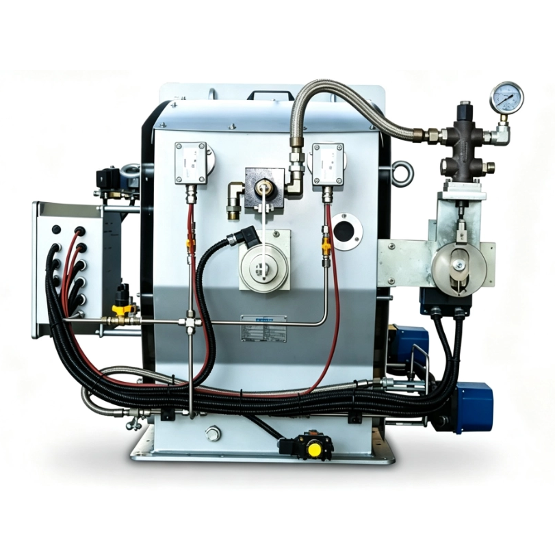
Parallel positioning provides accuracy, but it requires intelligent supervision. Managing a Gas and Oil Burner safely relies on cross-limiting control logic. Engineers often refer to this as lead-lag control. Without cross-limiting, rapid load changes can cause danger. If a sudden demand spike occurs, the boiler ramps up. If fuel enters the chamber faster than air, the mixture becomes rich. Unburned fuel accumulates. This creates a severe explosion hazard. Cross-limiting actively prevents this scenario.
The safety and stability mechanism operates on strict sequencing rules. The controller constantly monitors demand. It forces the air and fuel elements to follow a specific order during transitions.
Increasing load sequence: When demand rises, the system increases airflow first. The fuel flow only increases after the air damper reaches the required position. Air leads the fuel.
Decreasing load sequence: When demand drops, the system decreases fuel flow first. The air damper only closes after the fuel valve reaches its new, lower position. Fuel leads the air.
This evidence-oriented application guarantees a safe air-to-fuel ratio dynamically. The strategy utilizes highly responsive PID (Proportional-Integral-Derivative) loops. The PID loop continuously measures actual flow rates. It compares them against the stored combustion curve. If a valve sticks, the cross-limiting logic holds the other components back. This eliminates the risk of explosive fuel-rich conditions entirely. It also prevents flame blowouts caused by excessive sudden drafts. The burner remains perfectly stable, regardless of how aggressively the plant demand fluctuates.
Once you establish a safe baseline, you can focus on real-time optimization. Upgrading a Multi Fuel Burner often involves adding O2 trim and VFDs. These technologies react to environmental variables that a static curve cannot predict. They continuously fine-tune the combustion process. This maximizes fuel savings and further solidifies flame stability.
Understanding the key evaluation dimensions helps clarify their value. We must look at features compared to their actual outcomes.
Optimization Technology | Primary Function Mechanism | Direct Stability & Efficiency Benefit |
|---|---|---|
O2 Trim System | Continuous exhaust gas analysis via zirconium oxide probe. | Maintains precise stoichiometric ratio despite fuel quality or ambient temp shifts. |
Variable Frequency Drive (VFD) | Modulates the RPM of the combustion air fan motor directly. | Reduces electrical load and eliminates draft turbulence at partial loads. |
O2 trim serves a vital purpose. The continuous exhaust gas analysis measures remaining oxygen in the stack. Ambient temperature changes daily. Cold air is dense; hot air is thin. Fuel quality also fluctuates. The O2 trim system adjusts the air damper slightly to compensate. It maintains the perfect stoichiometric ratio constantly. Meanwhile, placing a VFD on combustion air fans yields massive improvements. Standard dampers throttle air by choking it. This creates turbulence and wastes electricity. A VFD slows the actual fan down instead. It reduces draft instability significantly. It also lowers electricity consumption at partial loads.
However, we must approach this with a skeptical angle. O2 trim is not a magic fix for a poorly tuned burner. Facility managers often make a common mistake here. They install O2 trim to correct underlying mechanical issues. You must view O2 trim strictly as a micro-adjustment tool. If your base combustion curve is poorly commissioned, the system fails. The O2 trim will constantly hunt for the right setting. It will swing the air damper wildly. This causes severe instability rather than fixing it. Always perfect the baseline curve first.
Selecting the right controller dictates the success of your upgrade. The market offers numerous options, from basic standalone units to complex programmable logic controllers (PLCs). You must apply rigorous shortlisting logic. You need to match the hardware capabilities to your facility’s specific operational profile.
Scalability and integration rank as top priorities. Consider your fuel transition needs. Does the controller support on-the-fly fuel switching? Some facilities need seamless transitions while maintaining load. Other systems require a full shutdown and purge cycle before firing a new fuel. A shutdown causes a temporary drop in steam pressure. Assess your integration capabilities with the existing plant DCS (Distributed Control Systems). Your operators need centralized data. Ensure the new BMS supports standard industrial protocols. Look for Modbus TCP, Profibus, or Ethernet/IP compatibility.
Security and compliance are non-negotiable elements. You must ensure the selected BMS complies with strict regional safety standards. In North America, UL and FM approvals are mandatory. The logic must satisfy NFPA 85 boiler and combustion systems hazards code requirements. For critical process industries, verify SIL 2 or SIL 3 (Safety Integrity Level) certifications. These ratings prove the controller's reliability under failure conditions.
Risk assessment requires evaluating the human element. Factor in operator training capabilities. A highly complex PLC-based control system offers infinite flexibility. However, it can drastically increase the risk of user error. If the HMI (Human-Machine Interface) is not intuitive, your existing maintenance crew will struggle. Complex alarm codes delay troubleshooting. Select a system with a touchscreen interface that provides clear, graphical diagnostic data.
We recommend several next-step actions before you solicit vendor bids. Conduct a comprehensive baseline combustion efficiency audit. You need to know your current baseline to measure future ROI. Also, review historical lockout logs. Identifying the exact scenarios that trip your current burner helps specify the new controller's requirements.
Achieving stable operation across multiple fuel types demands modern technology. A stable system relies entirely on removing outdated mechanical variables. You must implement digital, independent fuel-to-air ratio controls to succeed. Parallel positioning eliminates the physical wear and tear that degrades efficiency over time. It gives your boiler the precision it desperately needs.
Facility managers should view these upgrades as critical investments. We advise you to prioritize cross-limiting controls and parallel positioning. Treat them as the absolute minimum standard when retrofitting or replacing an industrial unit. Train your operators on the new HMI interfaces thoroughly. Ensure your baseline combustion curves are perfectly tuned before activating O2 trim. By following these steps, you guarantee safer operations, tighter emissions compliance, and substantial long-term fuel savings.
A: Yes, retrofitting is highly possible. You achieve this via an aftermarket linkageless controller and an upgraded burner head with a dual valve train. However, you must carefully evaluate the cost-benefit ratio. Sometimes, the labor and parts for a retrofit approach the cost of a completely new, highly efficient packaged unit.
A: Modern controllers handle this through strict sequencing logic. When switching to oil, the controller automatically sequences the introduction of atomizing media first. It proves that compressed air or steam pressure is adequate. Only after proving atomization pressure will it open the oil safety shut-off valves.
A: The typical return on investment ranges from 12 to 24 months. This is primarily driven by a 3–5% fuel savings from O2 trim optimization. You also gain reduced electrical costs via VFD integration and minimized unplanned downtime. Always ensure your ROI models properly account for initial commissioning and installation costs.
