

Views: 0 Author: Site Editor Publish Time: 2026-11-12 Origin: Site
Volatile energy markets drive unprecedented demand for resilient heating infrastructure. Sudden supply chain constraints make single-fuel reliance exceptionally risky. Industrial facilities need adaptable solutions to keep production moving during grid outages or fuel shortages. Different energy sources, like natural gas, light oil, and biomass, possess distinct calorific values. Switching fuels suddenly can easily compromise combustion efficiency. It often lowers expected heat output and disrupts strict emissions compliance. If you do not engineer the combustion system properly, changing energy sources causes costly downtime and mechanical failures. How do modern industrial facilities solve this complex challenge? They deploy highly adaptable combustion systems designed for rapid transitions. We will explore the technical mechanisms these systems use to dynamically manage varying heating values. You will also get a practical, evidence-based framework for evaluating commercial and industrial implementation.
Dynamic Calibration is Required: Efficient fuel switching relies on automated or precisely engineered air-to-fuel ratio controls to match the specific BTU/kWh of the active fuel.
Hardware Flexibility: True multi-fuel systems utilize specialized combustion heads and dual-delivery trains to process differing physical states (e.g., gas vs. liquid).
Output Variability: Changing fuels inherently impacts maximum heat output and turndown ratios; procurement must account for the lowest-calorific fuel in the planned rotation.
Compliance is Fuel-Specific: Adopting a multi fuel burner requires auditing emissions limits (NOx, particulates) for *all* intended fuel types, not just the primary source.
Single-fuel dependence exposes your facility to severe price spikes. Global energy markets fluctuate rapidly. Supply interruptions halt continuous operations and destroy daily profit margins. Integrating a Fuel Flexible Industrial Burner solves this business problem directly. Facility managers gain the ability to switch energy sources based on real-time market pricing.
To understand the operational economics, we must first define heating values technically. Engineers look at Gross Calorific Value (GCV) and Net Calorific Value (NCV). GCV includes the latent heat of water vapor produced during combustion. NCV excludes this latent heat. Burner design relies heavily on NCV. It dictates how much raw thermal energy the fuel actually yields inside the combustion chamber. When you switch from high-NCV natural gas to lower-NCV biogas, the system must process a significantly larger volume of fuel to achieve identical thermal output.
Implementing this flexible technology successfully requires hitting specific performance criteria. A poorly integrated system wastes money. A correctly engineered system protects revenue streams.
Success Criteria for Implementation:
Uninterrupted operational uptime: The transition between primary and backup fuels must occur rapidly. Automated systems should handle this without manual physical valve changes.
Thermal efficiency maintenance: The system must maintain acceptable baseline efficiencies. Burning a backup fuel should not waste excessive energy.
Predictable ROI modeling: Facility managers must calculate returns based on local fuel availability and cost arbitrage. Buying oil when gas prices peak requires a reliable system ready for immediate deployment.
Best Practice: Always negotiate fuel procurement contracts based on the flexible capabilities of your new equipment. You can secure favorable off-peak rates for secondary fuels if you can guarantee rapid usage when required.
Adapting to different heating values requires precise mechanical engineering and advanced software integration. The burner must manipulate airflow and fuel delivery simultaneously.
Different fuels demand completely different oxygen levels for complete combustion. Primary and secondary air volumes must shift accordingly. Primary air initiates combustion at the burner head. Secondary air shapes the flame and ensures complete fuel burnout.
A smart system uses variable speed drives (VSD) on combustion air fans. These drives adjust airflow dynamically based on the active fuel profile. They prevent rich firing, which wastes fuel and creates heavy soot. Soot accumulation quickly coats boiler tubes and drastically reduces heat transfer. They also prevent lean firing. Too much air cools the flame, lowers thermal efficiency, and increases unnecessary fan power consumption. VSD technology guarantees the air supply matches the exact oxygen requirement of the specific heating value.
Handling multiple physical states requires robust, specialized hardware. A highly engineered Gas and Oil Burner uses a dual-fuel setup. Liquid fuels behave entirely differently than gases. Liquid cannot burn directly; it must become a fine mist first.
Liquids require mechanical, steam, or air atomization. Atomization breaks the viscous liquid into microscopic droplets. Heavy fuel oils require aggressive steam atomization and pre-heating to achieve the correct droplet size for their heating value. Conversely, natural gas simply requires precise pressure regulation via a gas train. The combustion head manages both delivery streams seamlessly. It features distinct nozzles for liquids and lances for gas, ensuring neither delivery method compromises the other.
Modern industrial combustion relies heavily on advanced Burner Management Systems (BMS). Microprocessors and Programmable Logic Controllers (PLC) form the brain of the operation. They read fuel flow continuously. They adjust critical combustion parameters in real-time.
System engineers integrate O2 and CO trim sensors directly into the exhaust stack. These sensors feed live exhaust data back to the central BMS. If the system detects unburned carbon monoxide, the BMS instantly commands the variable speed drives to introduce more secondary air. This closed-loop feedback continuously optimizes the flame geometry. It ensures maximum efficiency regardless of subtle fluctuations in the fuel's calorific value.
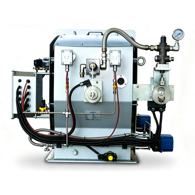
We must address heat output fluctuations honestly. Switching to a lower heating value fuel reduces the maximum capacity of your boiler or furnace. If you switch from high-yield natural gas to low-yield landfill gas, your boiler yields less heat per hour. The physical volume of gas required increases significantly. Eventually, the gas valves and piping reach their maximum physical flow limits. Once you hit this limit, the burner simply cannot push enough low-calorific fuel into the chamber to meet the original kW rating.
Turndown ratios also shift during fuel transitions. This ratio defines the operational flexibility between maximum and minimum firing output. A 10:1 ratio means the system can run efficiently at 10% of its maximum capacity. This range often narrows or widens depending on the active fuel. Highly volatile or heavy fuels might restrict the safe operating window to 4:1. This forces the system to cycle on and off more frequently during low-demand periods.
Efficiency trade-offs remain unavoidable. You will experience realistic efficiency drop-offs. Operating on secondary or backup fuels rarely matches the system's primary optimized fuel. We must avoid exaggerated performance claims. A system tuned perfectly for natural gas will lose marginal efficiency points when burning diesel.
Calorific Value Comparison and Performance Impact
Fuel Source | Typical Calorific Value (NCV) | Expected Output Impact | Optimal Turndown Ratio |
|---|---|---|---|
Natural Gas | High (~10 kWh/m³) | Baseline / 100% Capacity | Up to 10:1 |
Light Fuel Oil | Very High (~11.9 kWh/kg) | Minimal Capacity Loss | 8:1 to 10:1 |
Heavy Fuel Oil (HFO) | High (~11.2 kWh/kg) | Moderate Efficiency Loss | 5:1 to 6:1 |
Biogas / Syngas | Low (~5 to 6 kWh/m³) | Up to 40% Output Reduction | 3:1 to 5:1 |
Common Mistake: Facility operators often calculate their steam demand based on their primary high-calorific fuel. When grid disruptions force a switch to backup biogas, they fail to meet production demand because the boiler maxes out at a lower total output.
Changing fuels directly alters your exhaust profile. Switching from clean natural gas to heavy fuel oil creates immediate regulatory challenges. It instantly increases sulfur dioxide (SOx) and particulate matter (PM) emissions. Nitrogen oxide (NOx) levels also fluctuate depending on flame temperature and fuel-bound nitrogen.
Compliance teams must rigorously assess strict regulatory frameworks. Compare your equipment against regional environmental standards. Ecodesign regulations, the Medium Combustion Plant Directive (MCPD) in Europe, and EPA standards in the United States all apply. You must audit emissions limits for all operational fuels. Securing a permit for natural gas does not automatically grant you the right to burn diesel continuously during a shortage.
Combustion chamber compatibility represents another critical safety factor. Evaluate the physical geometry of your existing furnace or boiler carefully. Burning higher-calorific fuels often produces longer, wider flames. If your combustion chamber lacks adequate depth or width, flame impingement occurs. The flame physically strikes the boiler walls. This causes rapid metal degradation, localized overheating, and extreme safety hazards.
Conversely, burning a low-calorific fuel might result in an unstable, short flame. This fails to transfer radiant heat effectively to the rear of the boiler tubes. You must match the dual-flame profiles to the specific dimensional limits of the thermal vessel.
Facility upgrades require careful infrastructure planning. Adding a new energy profile is rarely a drop-in replacement. Dual-fuel capability demands extensive dual-piping networks. You often need distinct, blast-proof storage facilities. Liquid fuels demand stringent secondary containment protocols.
Heavy oils and certain biomass-derived liquids require dedicated fuel pre-treatment zones. You must install reliable oil pre-heaters to maintain correct viscosity before atomization. If the oil runs too cold, atomization fails. The fuel spits into the chamber, creating dangerous explosive pools rather than a controlled burn.
Maintenance overhead naturally increases. A Multi Fuel Burner involves significantly more mechanical parts than a single-fuel unit. Technicians must routinely remove and clean liquid fuel atomizers. They must purge fuel lines thoroughly with compressed air or steam after liquid fuel use. Leftover oil degrades, thickens, and creates hard blockages within the valving system.
How do you select the right equipment and avoid costly implementation errors? Follow this decision-stage shortlisting logic:
Audit peak load requirements strictly against the lowest-yield fuel: Determine your facility's absolute minimum thermal demand. Ensure the burner can hit this target even when operating on your lowest calorific backup fuel.
Verify control system interoperability: The new Burner Management System must talk seamlessly to your existing plant infrastructure. Ensure it communicates over modern protocols like Modbus or Profinet.
Assess physical chamber dimensions: Ask the manufacturer to provide simulated flame geometry models for both fuel types. Compare these dimensions against your existing boiler schematics.
Evaluate OEM support and local expertise: Dual-fuel systems require specialized commissioning. Ensure the manufacturer offers robust regional support, swift replacement part availability, and local technician training.
A multi-fuel combustion system functions as a highly engineered asset, not a simple plug-and-play gadget. It relies heavily on dynamic air modulation, precision atomization, and advanced control systems to manage fluctuating heating values effectively. When properly implemented, it shields industrial facilities from unpredictable energy markets and catastrophic supply chain failures.
Select equipment based on the output limits of the lowest-calorific fuel in your strategy.
Prepare your maintenance teams for inherent efficiency trade-offs and increased servicing routines.
Ensure your physical boiler geometry supports the varying flame dimensions produced by different fuels.
Never assume emissions permits cover secondary fuels without explicit regulatory approval.
Take proactive steps to protect your operational uptime. Request a comprehensive site audit or technical consultation from combustion experts today. A qualified engineer will calculate your required kW rating and map out the exact infrastructure modifications needed for your specific dual-fuel strategy.
A: Yes, slight efficiency changes occur naturally. Natural gas burns very cleanly and mixes effortlessly with air. Liquid fuels require energy-intensive mechanical atomization and pre-heating. However, modern systems utilize O2 trim sensors to continually adjust the air-to-fuel ratio. This automated, real-time calibration minimizes efficiency losses during the switchover process.
A: Often, yes. However, engineers must carefully evaluate the combustion chamber sizing. Higher calorific liquid fuels can significantly alter flame geometry, risking dangerous flame impingement on older boiler walls. Additionally, the existing boiler control panel must accept modern BMS integration to handle automated air modulation.
A: Modern units utilize automated changeover sequences controlled by the Burner Management System. The PLC halts the gas valves, initiates a rapid air purge, and sequentially opens the oil delivery train. VSD air dampers adjust instantly. Older setups might still require manual physical valve changes.
A: Absolutely. A boiler rated for 10 MW on high-yield natural gas might only produce 7 MW on low-calorific biogas. Your heat output capacity depends entirely on the fuel's specific energy density. Always size your thermal equipment based on the weakest fuel in your planned rotation.
