

Views: 0 Author: Site Editor Publish Time: 2026-09-02 Origin: Site
Improper flame geometry acts as a silent destroyer of critical boiler infrastructure. Poorly shaped flames cause premature refractory failure, dangerous tube ruptures, and highly costly unplanned downtime. Many facilities completely overlook this risk until catastrophic physical damage actually occurs. The core function of a modern Boiler Burner extends far beyond simply generating heat. It must distribute this heat safely. The flame envelope must fit the exact physical constraints inside the furnace chamber. Misaligned flames threaten equipment longevity and severely impact operator safety.
This guide serves as a practical evaluation framework. Facility managers and engineers can use it to upgrade or specify equipment effectively. You will learn to balance thermal efficiency, strict emission compliance, and prolonged equipment life. Proper geometry actively prevents localized overheating and thermal stress. Correct specifications keep your entire facility running smoothly, reliably, and safely. By understanding flame dynamics, you actively protect your most valuable thermal assets.
Flame Impingement is a Costly Liability: Direct flame contact with furnace walls or tubes degrades refractory materials and causes localized overheating.
Geometry Matches the Vessel: High-quality industrial boiler burners use adjustable air/fuel mixing to contour the flame specifically to the dimensions of the firetube or watertube furnace.
The Low NOx Trade-Off: Achieving lower emissions often changes flame length and width; selecting the right burner requires mitigating the risk of impingement.
CFD Modeling Reduces Retrofit Risk: Procurement evaluations should require Computational Fluid Dynamics (CFD) data from manufacturers to prove the flame shape fits the existing furnace prior to purchase.
Facility managers often focus purely on raw fuel expenses. They miss the severe operational risks surrounding poor flame geometry. An oversized flame causes immediate physical damage. It creates immense liabilities for daily operations. Direct costs associated here escalate rapidly. Production lines stop unexpectedly. Emergency repair crews charge premium rates. The damage compounds quietly over time.
Proper evaluation requires understanding specific failure points inside the combustion chamber. We can categorize these direct risks into three major areas.
Refractory Degradation: Improper flame spread creates intense thermal shock. Flames washing over brickwork cause severe temperature gradients. Refractory materials crack, blister, and spall rapidly. Facilities face frequent, expensive replacement projects. Damaged refractory also exposes outer steel casings to excessive heat.
Tube Impingement and Failure: Flames directly touching boiler tubes destroy the water's protective boundary layer. Engineers call this Departure from Nucleate Boiling (DNB). This localized boiling causes rapid scale buildup inside the pipe. Heat transfer drops drastically. Over time, metal fatigue leads to catastrophic tube ruptures. Such failures require immediate system shutdown and extensive welding repairs.
Efficiency Losses: A flame might be too short or too narrow. It fails to utilize available radiant heat transfer areas effectively. Heat escapes straight up the stack. The system consumes substantially more fuel to meet basic steam demand. This inefficiency drives up daily operating expenses considerably.
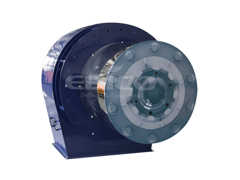
Modern combustion systems rely on precise aerodynamics. They shape the combustion zone without restricting overall output. The technical mechanism involves carefully manipulating air and fuel velocities. Advanced designs eliminate heavy academic guesswork. They provide tangible, adjustable parameters during operation.
Facility engineers must understand how internal hardware dictates external flame profiles. Different components manipulate different aerodynamic forces.
Component Name | Primary Aerodynamic Function | Effect on Flame Geometry |
|---|---|---|
Swirler / Diffuser | Induces rotational velocity in the air stream | Widens the flame and shortens its overall length. |
Variable Air Registers | Controls the ratio of primary to secondary air | Modifies flame stability and adjusts the combustion envelope. |
Gas Spuds / Nozzles | Determines fuel injection angle and velocity | Defines the primary combustion zone and flame origin point. |
Firing Head Blast Tube | Contains the initial mixing sequence | Prevents premature expansion and stabilizes the flame root. |
Engineers use swirl and airflow staging aggressively. Swirlers act as aerodynamic brakes. They force incoming air to spin rapidly. This spinning motion creates a low-pressure recirculation zone. It pulls hot combustion gases back toward the nozzle. High swirl creates a short, bushy flame. Low swirl allows the flame to stretch into a long, narrow pencil shape.
Fuel injection profiles matter equally. The positioning and angle of gas spuds dictate primary ignition. Oil nozzles utilize different spray angles to widen or narrow the droplet pattern. By swapping out nozzles, technicians can radically alter the heat release zone.
Adaptability remains a hallmark of premium equipment. A tier-one product allows for mechanical or electronic adjustments. Technicians fine-tune the flame shape during initial commissioning. They match the specific furnace chamber perfectly. This flexibility ensures safe operation across varying loads.
Environmental compliance forces facilities to reduce nitrogen oxide emissions aggressively. Traditional NOx reduction methods introduce serious geometry conflicts. Techniques like Flue Gas Recirculation (FGR) lower peak flame temperatures. Staged combustion spreads out the burning process over a larger volume. Both methods naturally tend to produce longer, cooler, and sometimes wider flames.
This creates a complex compliance versus geometry conflict. You cannot ignore physics. When you reduce the intensity of combustion, the flame must occupy more space to release the same amount of heat. This phenomenon makes retrofit projects highly complicated.
Retrofitting a standard, older furnace demands extreme caution. Installing a standard Low NOx Boiler Burner inherently changes the original flame profile. Without assessing existing geometry, new flames might lick the back wall. They could impinge directly on side tubes. This leads directly to the tube failures and refractory degradation mentioned earlier.
Buyers must evaluate vendors rigorously. Standard compliance is not enough. Advise your procurement team to look for "ultra-low NOx" solutions. These units must offer stabilized, compact flame patterns. Superior manufacturers engineer custom burner heads. They adapt their specialized designs to fit highly restrictive furnace dimensions. They utilize advanced metal alloys and precise gas injection to maintain a tight flame envelope while meeting stringent emission targets.
You need a concrete framework to evaluate various manufacturer proposals. Combustion upgrades require strict decision-stage criteria. Every facility has unique dimensional constraints. A unit performing perfectly in one plant might destroy the furnace in another.
Evaluation Criteria | Standard Approach | Best Practice Approach |
|---|---|---|
Flame Stability | Checked only at high fire. | Verified visually across the entire turndown range. |
Geometry Validation | Guesswork based on catalog specs. | CFD modeling simulating exact furnace dimensions. |
Controls Integration | Basic linkage adjustments. | Full integration into existing CCS for dynamic O2 trim. |
Emission Strategy | Massive FGR rates causing long flames. | Advanced internal mixing for compact low NOx flames. |
Upgrading your Industrial Boiler Burner requires checking multiple technical boxes.
Turndown Ratio & Flame Stability: The flame must maintain its engineered shape constantly. It needs stability across the entire firing range. A 10:1 turndown means it operates stably at 10% capacity. A collapsing, droopy flame at low fire poses a severe safety hazard. It can drop out and cause explosive fuel accumulation.
Vendor Engineering Capabilities (CFD): Insist on advanced simulation data before signing contracts. Manufacturers must provide Computational Fluid Dynamics (CFD) modeling. They should simulate the exact flame shape inside your specific furnace layout. CFD proves the design fits perfectly before manufacturing begins. It visualizes temperature contours and velocity vectors clearly.
Control System Integration: Modern setups require tight digital integration. Evaluate how the new hardware interfaces alongside existing Combustion Control Systems (CCS). Precision controls maintain optimal air-to-fuel ratios continuously. Parallel positioning systems prevent mechanical hysteresis. This precise control prevents flame distortion over years of operation.
Replacing heavy combustion equipment involves serious practical challenges. Installation requires much more than simply bolting on new hardware. The physical integration often reveals hidden mechanical issues. Old mounting plates might require structural reinforcement. Fuel trains usually need re-piping to meet modern safety codes.
Expert field tuning matters immensely. Even the finest equipment requires rigorous commissioning. Technicians must visually and instrumentally verify the flame shape on-site. They use specialized viewports to watch the flame under various loads. They insert combustion analyzers into the stack. They adjust air registers manually until the geometry matches the CFD predictions.
Draft and backpressure variations complicate performance daily. Changes in stack draft alter available combustion air. Barometric pressure drops during storms affect air density. Furnace backpressure shifts the predicted flame envelope entirely. Systems require dynamic tuning to compensate for environmental changes. Oxygen trim systems automatically adjust dampers to maintain shape.
Ongoing maintenance heavily protects your investment. Critical components degrade over time under extreme heat. Air diffusers warp out of shape. Oil nozzles clog from minor fuel impurities. Gas spuds accumulate carbon deposits. Strict maintenance schedules remain critical. Routine inspections prevent dangerous flame distortion years after the initial installation. Facility teams must clean and inspect the firing head annually.
Investing in correct combustion technology pays off heavily. It protects the much larger capital investment of the boiler vessel itself. Poor flame geometry destroys tubes and ruins expensive refractory linings. Proactive engineering completely prevents these expensive disasters. You must balance low emissions against safe heat distribution.
Initiate a thorough equipment replacement evaluation today. Request a baseline combustion audit from certified combustion engineers. Ask them for a complete furnace dimensional analysis. Demand CFD models for any proposed retrofit. Taking these actionable steps ensures prolonged equipment longevity, optimal fuel efficiency, and significantly safer daily operations.
A: Direct flame contact causes severe localized overheating. This heat breaks down the water's protective boiling boundary layer inside the tube. Without this boundary, scale bakes rapidly onto the metal. The material experiences extreme metal fatigue. This process inevitably leads to rapid, dangerous tube rupture and unplanned downtime.
A: A healthy flame features crisp, well-defined edges and a highly stable base. It must never touch the surrounding refractory or tubes. Color depends entirely on the fuel source. Gas flames should appear blue and translucent. Oil flames typically burn bright yellow or white. Stability remains the top visual indicator.
A: Flashback represents a severe mechanical malfunction. It occurs due to incorrect fuel and air velocities or faulty internal components. When the mixture burns too quickly, the flame travels backward into the housing. This requires an immediate system shutdown and a comprehensive mechanical inspection to prevent explosive hazards.
A: It does not always require a larger furnace. However, it demands highly careful engineering. Low NOx flames are inherently larger and longer. Installing them inside tight furnaces requires specific, compact-flame designs. Vendors must provide CFD validation to ensure the new flame fits perfectly without causing structural damage.
