

Views: 0 Author: Site Editor Publish Time: 2026-08-18 Origin: Site
Unlike steam boilers, thermal fluid heaters operate under entirely different stakes. They routinely reach extreme temperatures between 300°C and 400°C while maintaining incredibly low system pressure. This unique operating environment demands absolute precision from your heating equipment. Inadequate burner control directly causes localized overheating inside the coils. When this happens, you trigger thermal fluid degradation—specifically cracking and coking—which ruins process consistency and damages expensive infrastructure.
You cannot afford unstable heat flux in high-temperature manufacturing. Minor temperature deviations disrupt chemical reactions, compromise pharmaceutical yields, and force unexpected downtime. Our goal is to provide you with an evidence-based framework for evaluating these critical combustion systems. By the end of this guide, you will understand how to balance combustion stability, rigorous emission compliance, and extreme process temperature precision. This knowledge will help you protect your plant operations and extend the lifespan of your thermal fluids.
Protecting Fluid Integrity: Precise burner modulation prevents the boundary film temperature from exceeding safe limits, avoiding costly thermal oil cracking and system coking.
Control Technology Shift: Upgrading from traditional mechanical linkages to electronic parallel positioning systems significantly reduces hysteresis and optimizes the air-fuel ratio across the entire firing range.
Efficiency Automation: Integrating continuous O2 trim and air density compensation reduces stack losses, effectively lowering fuel consumption by compensating for ambient temperature shifts.
Process Impact: High turndown ratios and ±1°C temperature control capabilities are critical for yield quality in sensitive chemical, pharmaceutical, and food-grade applications.
Understanding the relationship between combustion output and fluid thermodynamics is essential. Your burner performance directly dictates the lifespan of your heat transfer fluid. A poorly tuned flame does more than waste fuel; it fundamentally alters the chemical structure of the oil.
You must distinguish between the bulk fluid temperature and the boundary layer temperature. The mass temperature represents the average heat of the fluid circulating through your system. The film temperature is the intense heat found right at the internal boundary layer of the heating coil. Under normal conditions, the film temperature sits roughly 5°C to 10°C higher than the mass temperature. The burner serves as the primary driver of this differential.
Unstable burner heat flux violently disrupts this delicate temperature balance. Harsh on/off burner cycles and poor flame modulation spike the radiant heat hitting the coil. This rapid energy transfer pushes the film temperature past the fluid’s thermal stability limit. When you exceed this threshold, the oil oxidizes and cracks.
Viscosity changes: Cracked oil generates light, volatile ends that drop the flash point.
Carbon buildup: Heavy degradation byproducts form coke on the inner coil walls.
Insulation effect: Coking acts as an insulator, forcing the burner to fire harder to reach the target mass temperature.
Combustion stability directly influences end-product quality. Industries like pharmaceuticals and specialty chemicals require strict ±1°C heating tolerances. You achieve this tight margin only when your burner output precisely matches the thermal load. Any fluctuation in the flame envelope translates into yield variations, ruining batches and shrinking profit margins.
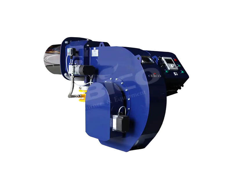
Selecting the right control strategy defines how well your system handles variable loads. Upgrading legacy controls often yields the fastest payback for plant operations.
Older systems rely on single-point mechanical actuators. A central motor uses physical linkages and cams to move both the fuel valve and the air damper simultaneously. Over time, these mechanical joints develop slop. This wear introduces severe hysteresis. The linkage cannot maintain precise air-fuel ratios during dynamic load changes, forcing operators to run the system with wasteful excess air just to ensure safe combustion.
Modern engineering abandons linkages in favor of electronic parallel positioning. This control scheme assigns independent servo motors to the fuel valves and the air dampers. A central microprocessor sends synchronized digital signals to these servos. They move precisely to pre-mapped combustion points. This eliminates hysteresis entirely. You achieve a highly repeatable air-fuel ratio at every point along the firing curve.
High-turndown burners drastically improve system longevity. A 10:1 turndown ratio means the burner can operate continuously at 10% of its maximum capacity. High turndown prevents the burner from shutting off during low-demand process phases. You avoid short-cycling, which otherwise introduces severe thermal shock to the refractory and the heating coils.
We must acknowledge the initial financial reality of these upgrades. Parallel positioning systems carry a higher upfront capital cost than basic mechanical linkages. However, the payback period is typically short. You justify the investment rapidly through sustained fuel savings, fewer maintenance interventions, and significantly extended thermal fluid life.
Comparison: Mechanical vs. Parallel Positioning Control | ||
Feature | Mechanical Linkages | Parallel Positioning |
|---|---|---|
Actuation Method | Single motor with physical cams | Independent digital servo motors |
Hysteresis Risk | High (joints wear over time) | None (digitally synchronized) |
Air-Fuel Precision | Poor during load transitions | Excellent across entire firing range |
Initial Capital Cost | Low | Moderate to High |
Every percentage point of efficiency lost translates into massive operational expenses. Real-world implementation variables constantly threaten your air-fuel ratio. You must actively manage these variables to reduce OPEX.
Stack losses represent the largest efficiency penalty in any heating system. This refers to the heat energy escaping up the flue rather than transferring to the thermal oil. Historically, unmanaged stack losses rob industrial systems of 10% to 30% of their total fuel energy. High excess air volumes cool the flame and carry valuable heat straight out the exhaust.
You solve excessive stack losses by implementing continuous exhaust gas monitoring. Automatic O2 trim systems use wet or dry basis sensors placed in the flue gas stream. They constantly measure the residual oxygen leaving the system. To fully optimize a Boiler Burner, you should follow this automated adjustment sequence:
Monitor: The sensor detects real-time O2 levels in the exhaust stream.
Analyze: The controller compares the reading against the ideal setpoint (usually 1.5% to 3.0% for natural gas).
Micro-adjust: The system sends a signal to the air damper servo to slightly restrict or increase airflow.
Stabilize: The combustion returns to peak efficiency without manual operator intervention.
Boiler rooms are dynamic environments. Day and night temperature shifts alter the density of the incoming combustion air. Cold night air is dense and oxygen-rich; hot afternoon air is thin. If you do not compensate for these shifts, your flame will oscillate between running too lean and dangerously rich. Automated air density trim systems act as mandatory safeguards, keeping combustion stable regardless of seasonal weather changes.
Environmental regulations demand lower emissions, but compliance must not compromise your process reliability. Navigating this requirement takes careful engineering.
Thermal NOx forms when nitrogen and oxygen react under extreme heat. To reduce NOx, you must lower the peak flame temperature. However, lowering combustion temperatures inherently impacts flame stability. If poorly engineered, this trade-off leads to flame flutter, delayed ignition, or sudden spikes in carbon monoxide (CO) emissions due to incomplete fuel burnout.
Modern low-emission designs solve this stability issue through staged combustion. An advanced thermal oil boiler burner utilizes staged air and staged fuel zones. The burner creates distinct rich and lean burn areas within the furnace. By spreading the combustion process out over a larger physical space, you control the flame envelope. This limits peak temperatures and starves the NOx formation process while maintaining a strong, stable flame front.
FGR pulls a portion of the cooled exhaust gas and injects it back into the combustion air stream. This acts as a thermal mass, absorbing heat and lowering the flame temperature. You must evaluate FGR integration constraints carefully. Excessive recirculation lowers the radiant heat transfer efficiency to your thermal coils. This forces the system to rely more heavily on convective heat transfer, which may not suit older furnace geometries.
Performance Chart: Emission Control Technologies Matrix | |||
Technology | Mechanism | Impact on Flame Stability | Radiant Heat Impact |
|---|---|---|---|
Standard Combustion | Rapid, concentrated mixing | Highly stable | Maximum radiant transfer |
Staged Combustion | Delayed fuel/air mixing zones | Moderate (requires precise tuning) | Slight reduction |
Flue Gas Recirculation | Injects inert gas to cool flame | Can cause flutter if ratio is too high | Noticeable reduction |
Your choice of fuel impacts everything from maintenance schedules to long-term energy security. You must evaluate fuel configurations based on plant infrastructure and regional supply reliability.
Natural gas serves as the industry baseline for clean, highly efficient combustion. When specifying a gas burner, you must understand your local fuel's Wobbe Index. The Wobbe Index measures fuel interchangeability. If the gas utility changes its supply blend, the Wobbe Index shifts. A burner tuned strictly for one index will struggle to maintain consistent heat release if the gas composition fluctuates.
Liquid fuels present unique implementation realities. Heavy oil boasts excellent energy density but requires extensive pre-heating systems to drop its viscosity. You must heat heavy oil sufficiently to ensure proper atomization at the nozzle. If atomization fails, large oil droplets cause heavy soot and coking. Light oil provides a cleaner alternative that avoids complex pre-heating. However, light oil subjects your operating budget to volatile market supply costs.
Many facilities prioritize energy security. Gas/oil switchable burners provide excellent risk mitigation against unexpected gas curtailments. If the utility cuts natural gas supply during peak winter demand, dual-fuel systems switch to backup liquid fuel seamlessly. You must weigh this security against the increased complexity of dual-valve trains. Dual systems demand stricter maintenance schedules to ensure the backup fuel nozzles remain clean and ready for deployment.
Even the best combustion equipment fails if integrated poorly. Execution realities dictate that your burner must communicate flawlessly with existing plant safeties.
Your new burner management system (BMS) must integrate seamlessly with the thermal oil system’s programmable logic controllers (PLCs). Thermal fluid heaters rely on critical interlocks to prevent catastrophic failures. The BMS must respond instantly to low-flow circulation pump trips. It must also tie into expansion tank nitrogen blanketing alarms. If fluid flow drops, the burner must shut down milliseconds before the stagnant oil cracks inside the hot coils.
Never accept a rushed commissioning phase. We recommend following standard EPA-style tune-up protocols. Your technicians must document "as-found" draft pressures, baseline emissions, and existing efficiency data before making adjustments. Only after establishing this baseline should they proceed with the "post-tune" mapping. This data proves the exact ROI of your control upgrades.
Combustion hardware degrades without routine care. You must prioritize accessible burner head designs during the procurement phase. Maintenance teams need easy access to inspect atomizing nozzles, air diffusers, and ignition electrodes. Regular inspection prevents carbon buildup, ensuring reliable ignition and preventing unscheduled downtime.
The right thermal oil boiler burner is far more than a simple heat source. It acts as a precision instrument that protects the capital investment of the thermal fluid itself. By mastering combustion thermodynamics, you prevent costly fluid degradation and secure process stability.
We advise procurement and engineering teams to take immediate action. First, audit your current turndown requirements to see if short-cycling is damaging your coils. Second, document your ambient boiler room conditions to evaluate the need for air density compensation. Finally, mandate parallel positioning controls for any new high-temperature system specifications. Taking these steps ensures your facility achieves absolute heating precision and long-term reliability.
A: The ideal ratio depends heavily on your process variability. However, we typically recommend a turndown ratio between 4:1 and 10:1. High turndown capability allows the burner to idle efficiently during low-demand phases. This prevents destructive thermal shock and eliminates short-cycling, extending the life of your heating coils.
A: Smooth, precise modulation prevents sudden spikes in radiant heat. When a burner transitions seamlessly between loads, it keeps the boundary layer film temperature well below the fluid's degradation point. This actively prevents thermal cracking, avoids coking, and drastically extends the operational lifespan of the fluid.
A: Yes, you can perform this retrofit. However, it requires careful engineering. You must evaluate the existing furnace geometry and draft capacity. Low NOx flames often have different shapes and radiant heat profiles. You must ensure the legacy coils can handle these altered flame dynamics without creating hot spots.
A: O2 trim systems continuously correct for external variables. They adjust the air-fuel ratio to counter variations in fuel heating value, barometric pressure, and combustion air temperature. This automation prevents the system from running with wasteful excess air or creating unsafe, soot-producing rich burns.
